What are Fly-by-Wire Systems?
Fly-by-wire is an automated flight control system that processes the command input made by either the pilot or autopilot and sends corresponding commands to the flight control surface actuators. This automated electronic arrangement replaces the traditional mechanical and hydraulic flight control systems (levers, rods, cables, and pulleys) for the pilot to remotely command the control surfaces.
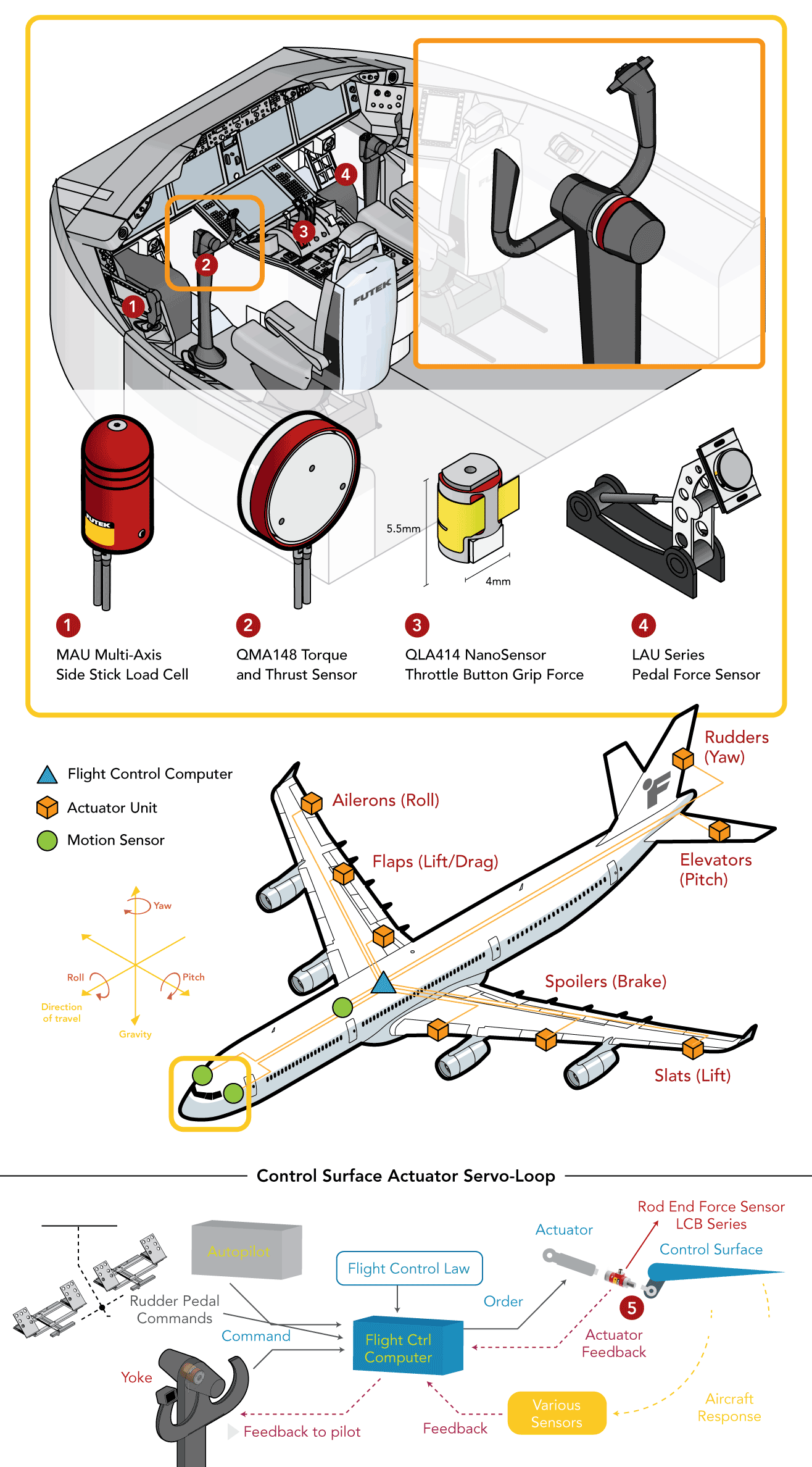
The aircraft’s flight control computer (FCC) monitors sensors throughout the aircraft to make automatic adjustments in the flight control surface actuators to enhance flight safety and performance, based on the flight control laws. FbW is basically an automated closed-loop control system and its basics elements are:
• Reference input provided by either the autopilot or pilot thru the yoke, side stick, pedals or any other actuation element;
• The Flight Control Computer (FCC), which calculates how much the current aircraft aerodynamic variables deviates from the reference input and what action should be commanded to the actuators to maneuver the aircraft safely according to the flight control laws;
• The surface control actuators, which translates the FCC signal command into hydro-mechanical force/torque to change the position/angle of the surface controls (Rudder, Elevators, Slats, Spoilers, Flaps, and Aileron). They are directly responsible to change the aircraft principal axis of rotation (Roll, Pitch, and Yaw);
• Instrumentation or aircraft sensors, which provide the response feedback to the FCC to compare with the reference input and estimate.
How are Force Sensors used in FbW Systems?
Multi-Axis force and torque sensors are frequently utilized in the flight test environment to validate the control system design based on the flight control laws. Load cells and multi-axis sensors are added to the control system during the verification and validation phase to verify and calibrate the fly-by-wire control loops parameters. Flight controls must be validated during the product design phase and require extreme auditing before in-flight use.
How it Works
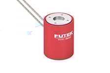
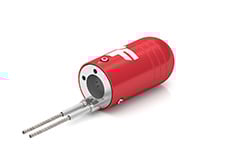
Side Stick: During the product validation phase, MAU300 Gear Shift Load Cell provides quality assurance and flight controls engineers with the appropriate tools to measure the force applied to side stick flight controls. To ensure that this mechanism is operating properly, FUTEK's MAU300 Multi-Axis Gear Shift Load Cell can be installed into the shaft of each flight control side stick.
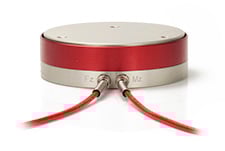
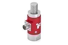
Yoke: Pilots rely heavily on the control column (yoke) to guide the pitch and roll of a plane. By rotating the yoke, the pilot maneuvers the roll axis. By propelling the yoke forward and backward, that pilot can adjust the elevation and pitch axis. To ensure that the control column is operating properly, quality assurance and flight controls engineers can install FUTEK's MBA500 Torque and Thrust Biaxial Sensor to measure the forces and torques applied to the yoke flight control. The MBA500 multi-axis force sensor performs measurements in both the Mz (the roll) and Fz (the pitch) directions.
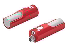
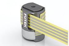
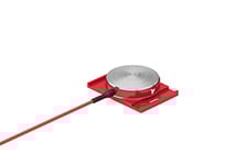
Throttle handle: The QLA414 Nanosensor or LMD300 Pinch Force Sensor can be used in the actuation buttons of the throttle handle to measure the pinching or pressing force exerted by the pilot.
Pedals: Pedals control the rudder control surface, which can move to the left and right by pushing the corresponding rudder pilot pedal. Utilizing LAU220 pedal force sensors allow engineers to audit the precision of these controls. Utilizing FUTEK's LAU pedal force sensors, quality assurance engineers can measure the force required to operate each rudder pedal flight control as it directs and propels the plane through flight.
Surface Controls Actuator: During the product design validation, the control engineer needs to measure the actuation force being applied to the control surface. This helps to ensure that the necessary force is being exerted and that the control loop is properly calibrated and will operate as expected. The LCB Rod End Load Cell is installed between the actuator and the flight control surface to measure the actual actuation force exerted and properly calibrate the actuator servo loop through additional force feedback.
Products in Use
• MAU300 Gear Shift Load Cell;
• MBA500 Torque and Thrust Biaxial Sensor;
• QLA414 Nanosensor;
• LMD300 Pinch Force Sensor;
• LAU220 Pedal Force Sensors;
• LCB400 Rod End Load Cell;
All these sensors can be paired with Signal Conditioner USB Digital Amplifier (USB225).

Contact Us
Please Contact Us with questions.
What are Fly-by-Wire Systems?
Fly-by-wire is an automated flight control system that processes the command input made by either the pilot or autopilot and sends corresponding commands to the flight control surface actuators. This automated electronic arrangement replaces the traditional mechanical and hydraulic flight control systems (levers, rods, cables, and pulleys) for the pilot to remotely command the control surfaces.
The aircraft’s flight control computer (FCC) monitors sensors throughout the aircraft to make automatic adjustments in the flight control surface actuators to enhance flight safety and performance, based on the flight control laws. FbW is basically an automated closed-loop control system and its basics elements are:
• Reference input provided by either the autopilot or pilot thru the yoke, side stick, pedals or any other actuation element;
• The Flight Control Computer (FCC), which calculates how much the current aircraft aerodynamic variables deviates from the reference input and what action should be commanded to the actuators to maneuver the aircraft safely according to the flight control laws;
• The surface control actuators, which translates the FCC signal command into hydro-mechanical force/torque to change the position/angle of the surface controls (Rudder, Elevators, Slats, Spoilers, Flaps, and Aileron). They are directly responsible to change the aircraft principal axis of rotation (Roll, Pitch, and Yaw);
• Instrumentation or aircraft sensors, which provide the response feedback to the FCC to compare with the reference input and estimate.
How are Force Sensors used in FbW Systems?
Multi-Axis force and torque sensors are frequently utilized in the flight test environment to validate the control system design based on the flight control laws. Load cells and multi-axis sensors are added to the control system during the verification and validation phase to verify and calibrate the fly-by-wire control loops parameters. Flight controls must be validated during the product design phase and require extreme auditing before in-flight use.