Pressure Measurement Sensor | How it works | FUTEK
What is a pressure measurement sensor? What are the different types of pressure measuring methods and pressure-sensing technologies and how do they work in pressure measurement?
Get to know the functionalities and capabilities of various pressure measurement sensors in this comprehensive guide.
Pressure Sensors are manufactured in the U.S. by FUTEK Advanced Sensor Technology (FUTEK), a leading sensor manufacturer of pressure transducers, utilizing one of the most advanced technologies in the Sensor Industry: Metal foil strain gauge technology. A pressure sensor is defined as a transducer that converts an input mechanical pressure into an electrical output signal (pressure sensor definition). There are several types of pressure sensors based on size, capacity, measurement method, sensing technology and output requirements.
What is a Pressure Measurement Sensor?
A pressure sensor is a transducer or instrument that converts an input mechanical pressure in gases or liquids into an electrical output signal. A pressure transducer consists of a pressure-sensitive element that can measure, detect or monitor the pressure being applied and electronic components to convert the information into an electrical output signal.
Pressure is defined as the amount of force (exerted by a liquid or gas) applied to a unit of “area” (P=F/A), and the common units of pressure are Pascal (Pa), Bar (bar), N/mm2 or psi (pounds per square inch). Pressure sensors often utilize piezoresistive technology, as the piezoresistive element changes its electrical resistance proportional to the strain (pressure) experienced.
How does a Pressure Measurement Transducer work?
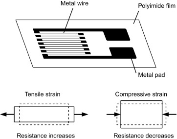
To understand how a FUTEK industrial pressure sensor works and how to measure pressure, firstly, one needs to grasp the underlying physics and materials science behind the pressure sensor working principle and piezoresistive effect, which is measured by the strain gauge (sometimes referred to as a strain gage). A metal foil strain gage is a transducer whose electrical resistance varies with applied force. In other words, it converts force, pressure, tension, compression, torque, and weight (aka weight sensors) into a change in electrical resistance, which can then be measured.
Strain gauges are electrical conductors tightly attached to a film in a zigzag shape. When this film is pulled, it — and the conductors — stretches and elongates. When it is pushed, it is contracted and gets shorter. This change in shape causes the resistance in the electrical conductors to also change. The strain applied in the load cell can be determined based on this principle, as strain gauge resistance increases with applied strain and diminishes with contraction.
Structurally, a pressure sensor is made of a metal body (also called flexure) to which the metal foil strain gauges are bonded. These force measuring sensors body is usually made of aluminum or stainless steel, which gives the sensor two important characteristics: (1) provides the sturdiness to withstand high loads and (2) has the elasticity to minimally deform and return to its original shape when the force is removed.
A pressure sensor converts pressure into an electrical signal. FUTEK industrial pressure sensors utilize the piezoresistive effect, which comprises of metal foil strain gauges mounted onto a diaphragm. As pressure changes, the diaphragm changes shape, causing the resistance in the strain gauges to change, allowing the pressure changes to be measured electrically. Our pressure sensors naturally produce an electrical signal in millivolts that varies proportionally with the load and the sensor excitation voltage (mV/V – millivolt per volt). However, we offer pressure sensors with internal analog amplifiers. The pressure sensors with built-in amplifiers generate signals either in varying voltage, i.e. ±10V, or varying current, i.e. 4-20 mA. However, if your application requires a digital or USB pressure sensor amplifier, please refer to our force sensors instruments and Amplifiers store page.
The strain gauges are arranged in what is called a Wheatstone Bridge Amplifier Circuit (see below animated diagram). This means that four strain gages are interconnected as a loop circuit and the measuring grid of the force being measured is aligned accordingly.
The strain gauge bridge amplifiers provide regulated excitation voltage and convert the mv/V output signal into another form of signal that is more useful to the user. The signal generated by the strain gage bridge is a low strength signal and may not work with other components of the system, such as PLC, data acquisition modules (DAQ) or computers. Thus, pressure sensor signal conditioner functions include excitation voltage, noise filtering or attenuation, signal amplification, and output signal conversion.
Furthermore, the change in the pressure sensor amplifier output is calibrated to be proportional to the force applied to the flexure, which can be calculated via the pressure sensor circuit equation.
What are the types of pressure measurement sensors?
Pressure sensors can be classified in terms of the type of pressure measurements they gauge as well as the pressuring-sensing technology the transducer operates.
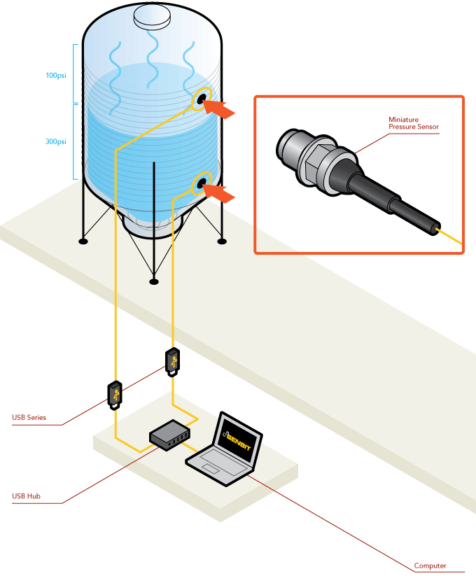
Differential Pressure Sensor: Differential pressure is a measurement of the pressure difference between two pressure values or two pressure points in the system, thus measuring by how much the two points differ from each other, not their magnitude relative to atmospheric pressure or to another reference pressure such as absolute vacuum. This is different from a static or absolute pressure sensor that would measure pressure using just one port and typically differential pressure sensors are packaged with two ports to which pipes can be attached and connected to the system in two distinct pressure points from where the differential pressure can be measured and calculated.
This pressure measuring approach is typically used to measure the flow of a liquid or a gas in pipes or ducts.
Absolute or Vacuum Pressure Sensor: This sensor measures the absolute pressure, which is defined as the pressure measured relative to a perfect sealed vacuum. Absolute pressure sensors are used in applications where a constant reference is required. These applications require reference to a fixed pressure as they cannot be simply referenced to the surrounding ambient pressure. For example, high-performance industrial applications such as monitoring vacuum pumps, liquid pressure measurement, industrial packaging, industrial process control and aerospace and aviation inspection use this technique. When it comes to measuring air pressure, specifically for applications such as barometric measurements for weather or in altimeters, an absolute pressure sensor is the device of choice.
Gauge or Relative Pressure Sensor: Gauge pressure is simply a special case of differential pressure with pressures measured differentially but always relative to the local ambient pressure. In the same respect, absolute pressure can also be considered a differential pressure where the measured pressure is compared to a perfect vacuum. Changes of the atmospheric pressure due to weather conditions or altitude directly influence the output of a gage pressure sensor. A gauge pressure higher than ambient pressure is referred to as positive pressure. If the measured pressure is below atmospheric pressure it is called negative or vacuum gage pressure.
Types of pressure-sensing technologies or working principles
There are a variety of pressure-sensing technologies or sensing principles capable of transducing pressure into a measurable and standardized electrical signal. This article will focus on the force collector types, which are the ones that use a force gauge (i.e. diaphragm) to measure strain (or deflection) due to applied force over an area (pressure).
Resistive or piezoresistive effect: Resistive pressure measurement sensors utilize the change in electrical resistance of a strain gauge bonded to the diaphragm (also known as a flexure element) that is exposed to the pressure medium.
The strain gauges often comprise of a metal resistive element on a flexible backing bonded to the diaphragm (i.e. metal foil strain gage), or deposited directly using thin-film processes.
Normally, the strain gauges are connected to form a Wheatstone bridge circuit to maximize the output of the sensor and to reduce sensitivity to errors. This is the most commonly employed sensing technology for general-purpose pressure measurement and uses the same principle of how a load cell works.
Capacitive: Capacitive pressure sensors use a diaphragm that is deflected by the applied pressure to create a variable capacitor to detect strain due to applied pressure. As pressure is applied, the external force compresses the diaphragm, and the capacitance value decreases. As the pressure is released, the diaphragm returns to its original shape and capacitance follows. Common technologies use metal, ceramic, and silicon diaphragms. The capacitance can be calibrated to provide accurate pressure reading.
Capacitive sensors, which display a capacitance change as one plate deflects under applied pressure, can be highly sensitive and withstand large overloads. Constraints on materials, and joining and sealing requirements, however, can restrict applications.
Piezoelectric effect: Piezoelectric pressure sensors utilize the property of piezoelectric materials like ceramic or metallized quartz, to generate an electrical potential on the surface when the material is subjected to mechanical stress and strain is generated. The charge magnitude is proportional to the load applied, and the polarity is defined by the force direction. The electrical potential accumulates and dissipates quickly as pressure changes, allowing measurement of fast-changing dynamic pressures.
Please note that piezoelectric effect is different from piezoresistive effect. Although both terminologies are associated to the effects of pressure applied on materials (piezo is derived from the Greek word for physical pressure), piezoresistive effect is related to the change in the electrical resistance while piezoelectric effect is related to the production of electrical potential (voltage charge) in the material.
Pressure measurement standards
Pressure is typically measured in units of force per unit of surface area ( P = F / A). In physical science the symbol for pressure is p and the SI unit for measuring pressure is pascal (symbol: Pa). One pascal is the force of one Newton per square meter acting perpendicular on a surface. Other commonly used pressure units for stating the pressure level are psi (pounds per square inch), and bar. Use of pressure units have regional and application preference: psi is commonly used in the United States, while bar the preferred unit of measure in Europe.
| Pascal | Bar | Standard atmosphere | Pound per square inch | |
|---|---|---|---|---|
| (Pa) | (bar) | (atm) | (psi or lbf/in2) | |
| 1 Pa | 1 | 10−5 bar | 9.8692×10⁻⁶ atm | 1.45 x 10⁻⁴ |
| 1 bar | 100,000 | 1 | 0.98692 | 14.5038 |
| 1 atm | 1013.25 | 1.01325 | 1 | 14.6959 |
| 1 psi or lbf/in2 | 6,894.76 | 0.06894 | 0.06804 | 1 |
Why is it important to calibrate pressure measurement sensors?
Pressure measurement sensor calibration is an adjustment or set of corrections that are performed on a sensor, or instrument (amplifier), to make sure that the sensor operates as accurately, or error-free, as possible.
Every pressure measurement sensor is prone to measurement errors. These structural uncertainties are the simply algebraic difference between the value that is indicated by the sensor output versus the actual value of the measured variable, or known reference pressures. Measurement errors can be caused by many factors:
Zero offset (or pressure sensor zero balance): An offset means that the sensor output at zero pressure (true zero) is higher or lower than the ideal output. Additionally, zero stability relates to the degree to which the transducer maintains its zero balance with all environmental conditions and other variables remaining constant.
Linearity (or non-linearity): Few sensors have a completely linear characteristic curve, meaning that the output sensitivity (slope) changes at a different rate throughout the measurement range. Some are linear enough over the desired range and does not deviate from the straight line (theoretical), but some sensors require more complex calculations to linearize the output. So, pressure sensor non-linearity is the maximum deviation of the actual calibration curve from an ideal straight line drawn between the no-pressure and rated pressure outputs, expressed as a percentage of the rated output.
Hysteresis: The maximum difference between transducer output readings for the same applied pressure; one reading is obtained by increasing the pressure from zero and the other by decreasing the pressure from the rated output. It usually measured at half rated output and expressed as a percentage of the rated output. Measurements should be taken as rapidly as possible to minimize creep.
Repeatability (or non-repeatability): The maximum difference between transducer output readings for repeated inputs under identical pressure and environmental conditions. It translates into the pressure measurement sensor's ability to maintain consistent output when identical pressure are repeatedly applied.
Temperature Shift Span and Zero: The change in output and zero balance, respectively, due to a change in transducer temperature.
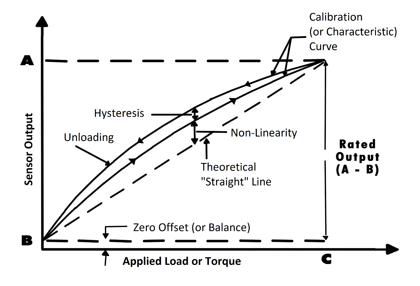
Each pressure sensor has a "characteristic curve" or a "calibration curve", which defines the sensor's response to an input. During a regular calibration using the pressure measurement sensor calibration machine, we check the sensor's zero offset and linearity by comparing the sensor output under reference weights and adjusting the sensor response to an ideal linear output. The pressure sensor calibration equipment also check hysteresis, repeatability and temperature shift when customers request it for some critical pressure measurement applications.
For more information about calibration, please refer to our Sensor Calibration FAQ Page.
If you have further questions about calibration terms and definitions, please refer to our Sensor Calibration Terms Glossary.
Want to know what calibration services we offer for your sensor and/or system?
How often should a pressure measurement sensor be recalibrated?
As strain gauge pressure measurement sensor are exposed to continuous usage, aging, output drift, overload and improper handling, FUTEK highly recommends a yearly recalibration interval. Frequent recalibration helps confirm whether the sensor maintained its accuracy over time and provides a load cell calibration certificate to show that the sensor still meets specifications.
However, when the sensor is used in critical applications and harsh environments, pressure sensors may require even more frequent calibrations. Please consult appropriate calibration intervals with our Technical Support team, who will help you evaluate the most economical calibration service interval for your pressure measurement sensor.