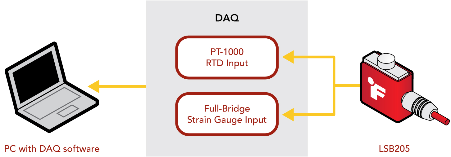
FUTEK has integrated the PT-1000 Resistance Temperature Detector (RTD) into its latest products to allow for continuous environment monitoring and to detect variations in temperature. You will The PT-1000 RTD is currently integrated into several products, including the LSB205 Jr S-Beam Load Cell and LSM305 Parallelogram Load Cell.
What is the PT-1000 RTD?
A PT-1000 Resistance Temperature Detector (RTD), is a temperature sensor made from a fine platinum wire which has a nominal resistance of 1000 Ohm at 0°C. As the temperature changes, the resistance of the wire changes approximately linearly due to the properties of platinum.
PT-1000 RTD delivers reliable performance in a 2-wire configuration, with its high 1000 Ohm resistance minimizing the impact of connecting wire lengths on system resistance. While a 4-wire setup can provide additional compensation for wire resistance in some applications, the PT-1000 is optimized for 2-wire use.
How do you interface with it?
While it is possible to utilize an ohmmeter to correlate the resistance change to temperature, doing so comes with caveats. Any device for measuring RTD resistance must minimize the voltage and current injected into the RTD, otherwise heating from electrical resistance will skew the readings. Instead, use a specialized integrated circuit (IC) with the correct reference resistor for a PT-1000 RTD to maximize the accuracy of RTD measurements.
How do you calibrate it?
Once you have a sensor with an RTD and a device to measure the RTD’s resistance, you need to calibrate the RTD. To do that, you need a temperature-controlled chamber and a calibrated temperature probe with the capability of measuring the RTD resistance.
Next, you need to select a few temperature testing points. It’s recommended that you select 0˚C/32˚F as one temperature point, as that is the baseline temperature/resistance correlation for the RTD. For example, you might choose 37.8˚C/100˚F as the second temperature point, representing the highest temperature sensor is expected to encounter.
Next, you place the sensor into the chamber, place the reference temperature sensor as close as possible to the RTD, and perform the following steps:
- Connect the sensor to a power supply with necessary excitation voltage and allow the sensor to warm up.
- Set the temperature chamber to slowly ramp down to 0˚C/32˚F and have it soak for up to 20 minutes.
- Slow ramping and long soak times ensure stable, more accurate RTD readings.
- Measure the RTD resistance and the reference temperature reading and record both values, for example a resistance measurement of 1032 Ohm at 0˚C.
- Ramp the chamber slowly up to 37.8˚C/100˚F and have it soak for up to 20 minutes. Measure the RTD resistance and the reference temperature reading and record both values, for example a resistance measurement of 1132 Ohm at 37.8˚C.
How do you correlate its output?
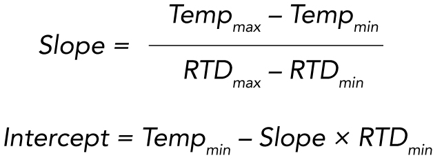
Now you can establish an accurate resistance to temperature conversion for your RTD. This conversion is performed with the following equation using the resistance and temperature values captured earlier:
Temperature = Slope × RTD Resistance + Intercept
Note that the above applies to temperatures above freezing, as RTD sensors will have different slopes for above freezing and below freezing. When operating below freezing, a second temperature correlation must be established, using the same method as above with a subzero temperature as the second data point.
Going further, by loading the sensor with a known load and observing the output at different temperature points, you can correlate force change per resistance change, or temperature change.
For example, if you find that the load will change 10lbs over 100 ohms, that will help you estimate a prediction of how much the force readings from the sensor will change per degree temperature.
What’s next?
For more information on our sensors with the PT-1000 RTD, as well as our complete line of sensors and instruments, contact FUTEK Sales at: (949) 297-9658 or futek@futek.com.
Example setup
Drawing Number: ER1204