Torque Sensors
How do the different types of torque sensors (a.k.a. "torque cell") used for torque measurement and what are the differences between them? We outline the most important facts in this comprehensive introduction to torque transducers for measuring torque.
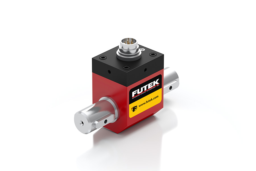
Torque Sensors manufactured in US by FUTEK Advanced Sensor Technology (FUTEK), a leading manufacturer producing a huge selection of Torque Transducers, utilizing one of the most advanced technologies in the Sensor Industry: Metal foil strain gauge technology. It is is defined as a transducer used for torque measurement (aka torque sensing) that converts an input mechanical torque into an electrical output signal. Torsions Sensors are also commonly known as Torque Transducer, Torque Cell or Moment Sensor. There are two main types of Torque Sensors: Reaction Torque Sensors or Rotational Torque Sensors.
By definition, torque sensor is a type of transducer, specifically a torque transducer that converts a torque measurement (reaction, dynamic or rotary) into another physical variable, in this case, into an electrical signal that can be measured, converted and standardized. As the torque applied to the sensor increases, the electrical output signal changes proportionally (aka torque detector or torque gauge).
There are two main categories of Torsions Sensors: rotary torque sensor and reaction torque sensors. In summary, a reaction sensor measures stationary torque (static or non-rotational), and rotary measures rotational torque (dynamic torque sensor).
Understanding the application and defining the requirements is a crucial part of how to select a torque sensor.
Rotary Torque Sensors (dynamic or rotational torque)
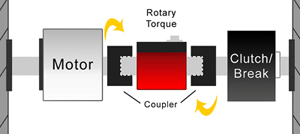
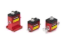
Rotational sensors (or dynamic torque sensor) are utilized in applications where the torque measurement must be taken at a spinning shaft, engine or a stationary motor. In this case, the transducer must rotate in-line attached to the shaft. A rotary torque transducer is fitted with a slip ring or wireless electronics to transmit the torque signal while rotating, functioning as a non contact torque sensor.
Rotary Torque Transducers are frequently used as testing/auditing tools for motors, power tools, turbines, torque measuring tool (or torque measurement tool) and generators to measure rotational torque. A shaft-to-shaft Rotating Torque Tester can be also utilized for torque feedback control, torque auditing, and analyzing the efficiency of test stands (i.e. torque analyzer).
How to measure torque of a motor? The Rotating Torque measurement (aka rotary torque measurement) is coupled between the motor and the load. As the shaft spins, the Torsions Sensor measures the torque produced by the motor in response to the load applied to the rotating shaft. Some Rotary Sensors are equipped with built-in encoders. These encoders measure the angle/speed produced during the test. Torsion measurements can successfully be monitored on a local digital display, such as a Panel Mount Display, a Handheld Display, connected to a PLC, or streamed to a PC using a digital USB instrument.
Rotary Torque Transducer is also a crucial part of dynamometers (or dyno for short), as it provides torque measurement and angular speed (RPM) to easily calculate output power, allowing accurate calculation of motor or engine performance in Kw or HP as well as its electromechanical efficiency.
In some instances, the user wants to measure the electric motor output power. In that case, one may want to use a rotary torque sensor with encoder and a Universal Signal conditioner to read both torque and angular speed (RPM). Check out this application note on how to measure the electric motor output power.
Reaction Torque Sensors (static)
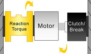
In some applications, the torque measurement taken with an in-line rotary sensor may be measured at the point where the torque is transferred to the ground using a reaction torque transducer (static torque measurement).
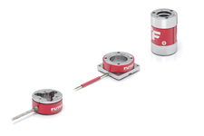
A reaction torsion sensor (not LVDT displacement sensors nor a draw wire sensor) has two mounting flanges (flange-to-flange sensor). One face is fixed to the ground or a rigid structural member and the other to the rotating shaft or rotary element. Rotation generates shear forces between the flanges, which is captured by the foil strain gauges bonded to the sensor beams and transduced into electrical current by the Wheatstone bridge.
For a given application, a reaction sensor (aka moment sensor) is often less complex and, therefore less expensive than a rotary sensor. Reactionary torque transducers are frequently used as a torque calibration tool or as torque wrench calibration tool. Reaction Torque sensors can also be used as miniature electrical torque screwdrivers, allowing Engineers to have live feedback of the torque and/or do study the torque applied during assembly. The automotive industry uses steering torque sensors for Steer by Wire systems validation and verification and other car sensors applications (automotive sensors). FUTEK also customizes light-weight low-profile embedded high-precision strain wave harmonic gearing torque sensors for closed-loop feedback with high flexibility on geometry and design.
Other applications that use reaction torque sensors are:
For miniaturized versions of load cell and force sensors, visit our miniature sensors overview page.
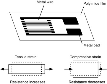
Firstly, we need to understand the underlying physics and material science behind the rotary torque sensor working principle, which is the strain gauge (sometimes referred to as Strain gage). Metal foil strain gauge is a sensor for measuring force whose electrical resistance varies with applied force. In other words, it converts force, pressure (Check our "What is a pressure sensor?" guide), tension, compression, torque, weight (aka weight sensors), etc… into a change in electrical resistance, which can then be measured. This is the basic principle behind how to measure torque.
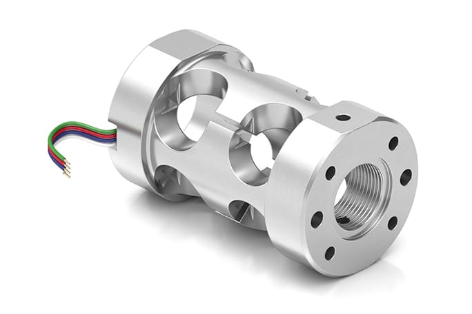
Structurally, a reaction torsion sensor is made of a metal body (also called flexure) to which foil strain gauges are bonded. The sensor body is usually made of aluminum or stainless steel, which gives the force transducer two important characteristics: (1) provides the sturdiness to withstand high torques; and, (2) has the elasticity to minimally deform and return to its original shape when the torque is removed.
When torque is applied (clockwise or counterclockwise), the metal body acts as a “spring” and is slightly deformed, and unless it is overloaded, it returns to its original shape. As the flexure deforms, the strain gage also changes its shape and consequently its electrical resistance, which creates a differential voltage variation through a Wheatstone Bridge circuit. Thus, the change in voltage is proportional to the torque applied to the transducer, which can be calculated via the torque sensor circuit voltage output.
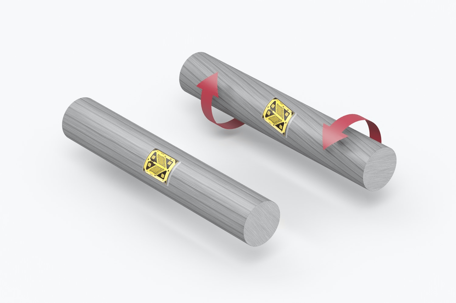
In a Rotary Torque Sensor, the strain gauge is bonded to the rotating shaft that slightly deforms when torque is applied. The shaft deflection induces stress in the strain gauge that changes its resistance. A combination of strain gauges (usually 4) is arranged in an electrical circuit, the Wheatstone bridge amplifier, that converts the resistance variations into a voltage output, which can be calibrated and measured.
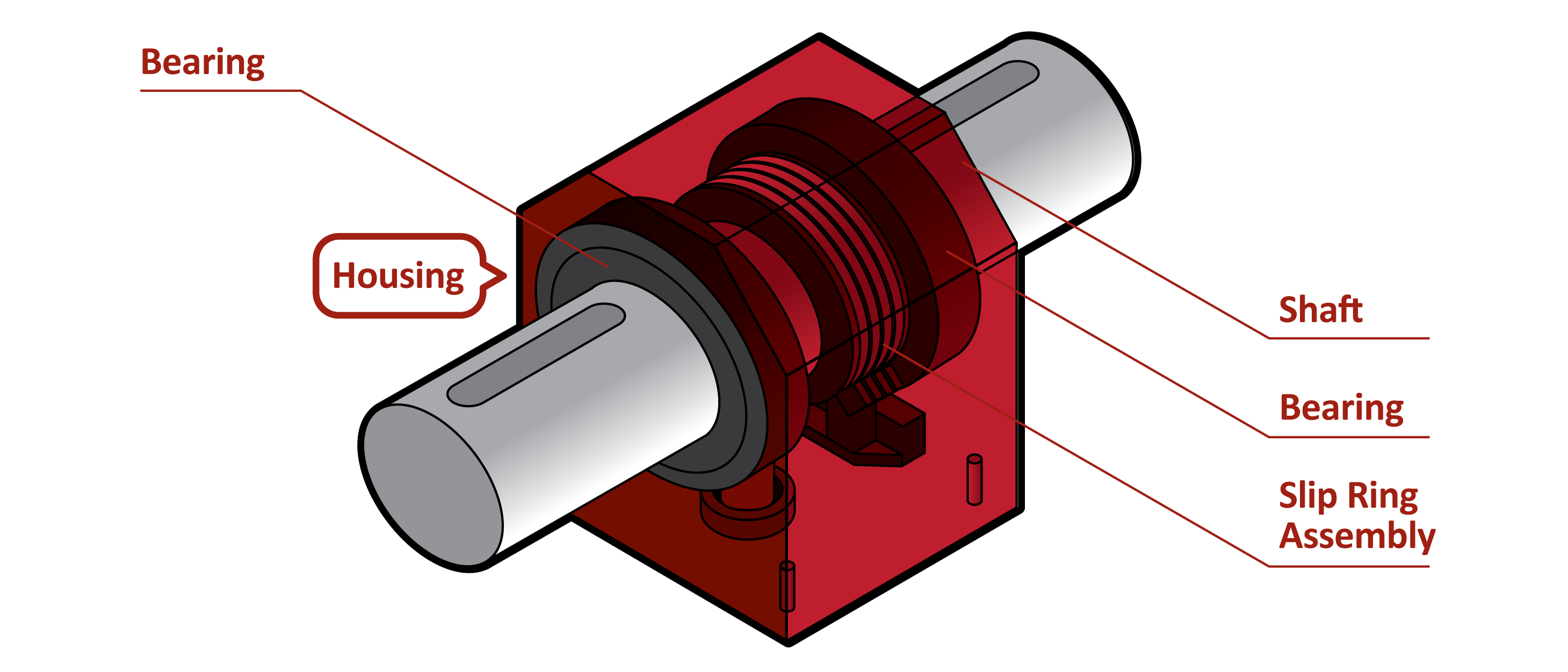
Rotary Torque Sensors are designed to torque measurement, and function as torque sensor for rotating shaft. Thus, it is necessary to transfer power to the strain gauge bridge, as well as a means to receive the signal from the rotating torque meter or shaft. This can be accomplished using slip rings, wireless telemetry, or rotary transformers. Optionally, sensors can also embed encoder for angle or speed measurement.
The sensors must be carefully designed seeking to eliminate off-axis loading (also called side loads or extraneous moments), and must be sensitive only to counterclockwise and counterclockwise torque loading. The sensor output is a function of force and distance (T=F x d), and is usually expressed in inch-pounds (in-lb)., foot-pounds (ft-lb) or Newton-meters (N.m).
For further information, watch our webinar on "How Torque Sensors works".
A question that we frequently hear is: “What is the right sensor for my application?” The reason why it gets asked so often is that it can be tricky to navigate the various sensor offerings on the market. So, be it a small torque sensor or a high capacity torque sensors, make sure to follow the steps below for adequate torque sensor sizing.
To help you select your load cell, FUTEK developed an easy to follow, 4-Steps guide. Here is a glimpse to help you narrow down your choices. Check out our “How to choose a Torque Sensor” complete guide for further information.
- Step 1: Understand your application and what you want to measure or control. Firstly, understand your application and define the type of torque you want to measure — reaction torque or rotary torque? Also, what is the environment (temperature, pressure, humidity). The application may require underwater torque sensors. Pressure sensors may also be required.
- Step 2: Define the sensor mounting characteristics and its assembly. How will you be mounting the sensor? (Flange to flange, square drive, shaft to shaft, hex drive, etc.) Will you be using this clockwise, counterclockwise, or both?
- Step 3: Define your minimum and maximum capacity and key requirements. Be sure to select the capacity over the maximum operating torque and determine all extraneous load (side loads or off-center loads) and moments prior to selecting the capacity. Also, what is your max RPM required? Do you need to measure speed and angle position?
- Step 4: Define the type of output your application requires. Some sensors outputs a mV/V signal, which can be paired with an amplifier for up to ±10VDC, while other non-contact rotational sensors will provide ±5VDC output . So, if your PLC or DAQ requires analog output, digital output (i.e.: digital torque sensor) or serial communication, you will need a torque sensor amplifier or signal conditioner. Make sure to select the right amplifier as well as calibrate the entire force measurement system (sensor + signal conditioner). This turnkey solution translates into more compatibility and accuracy of the entire torque measurement system.
After the selection, make sure to have the sensor calibrated by an accredited torque sensor calibration lab.
For more details on our 4-Steps Guide, please visit our How to choose a Torque Sensor” complete guideline.
By definition, torque sensor is a type of transducer, specifically a torque transducer that converts a torque measurement (reaction, dynamic or rotary) into another physical variable, in this case, into an electrical signal that can be measured, converted and standardized. As the torque applied to the sensor increases, the electrical output signal changes proportionally (aka torque detector or torque gauge).
There are two main categories of Torsions Sensors: rotary torque sensor and reaction torque sensors. In summary, a reaction sensor measures stationary torque (static or non-rotational), and rotary measures rotational torque (dynamic torque sensor).
Understanding the application and defining the requirements is a crucial part of how to select a torque sensor.
Rotary Torque Sensors (dynamic or rotational torque)
Rotational sensors (or dynamic torque sensor) are utilized in applications where the torque measurement must be taken at a spinning shaft, engine or a stationary motor. In this case, the transducer must rotate in-line attached to the shaft. A rotary torque transducer is fitted with a slip ring or wireless electronics to transmit the torque signal while rotating, functioning as a non contact torque sensor.
Rotary Torque Transducers are frequently used as testing/auditing tools for motors, power tools, turbines, torque measuring tool (or torque measurement tool) and generators to measure rotational torque. A shaft-to-shaft Rotating Torque Tester can be also utilized for torque feedback control, torque auditing, and analyzing the efficiency of test stands (i.e. torque analyzer).
How to measure torque of a motor? The Rotating Torque measurement (aka rotary torque measurement) is coupled between the motor and the load. As the shaft spins, the Torsions Sensor measures the torque produced by the motor in response to the load applied to the rotating shaft. Some Rotary Sensors are equipped with built-in encoders. These encoders measure the angle/speed produced during the test. Torsion measurements can successfully be monitored on a local digital display, such as a Panel Mount Display, a Handheld Display, connected to a PLC, or streamed to a PC using a digital USB instrument.
Rotary Torque Transducer is also a crucial part of dynamometers (or dyno for short), as it provides torque measurement and angular speed (RPM) to easily calculate output power, allowing accurate calculation of motor or engine performance in Kw or HP as well as its electromechanical efficiency.
In some instances, the user wants to measure the electric motor output power. In that case, one may want to use a rotary torque sensor with encoder and a Universal Signal conditioner to read both torque and angular speed (RPM). Check out this application note on how to measure the electric motor output power.
Reaction Torque Sensors (static)
In some applications, the torque measurement taken with an in-line rotary sensor may be measured at the point where the torque is transferred to the ground using a reaction torque transducer (static torque measurement).
A reaction torsion sensor (not LVDT displacement sensors nor a draw wire sensor) has two mounting flanges (flange-to-flange sensor). One face is fixed to the ground or a rigid structural member and the other to the rotating shaft or rotary element. Rotation generates shear forces between the flanges, which is captured by the foil strain gauges bonded to the sensor beams and transduced into electrical current by the Wheatstone bridge.
For a given application, a reaction sensor (aka moment sensor) is often less complex and, therefore less expensive than a rotary sensor. Reactionary torque transducers are frequently used as a torque calibration tool or as torque wrench calibration tool. Reaction Torque sensors can also be used as miniature electrical torque screwdrivers, allowing Engineers to have live feedback of the torque and/or do study the torque applied during assembly. The automotive industry uses steering torque sensors for Steer by Wire systems validation and verification and other car sensors applications (automotive sensors). FUTEK also customizes light-weight low-profile embedded high-precision strain wave harmonic gearing torque sensors for closed-loop feedback with high flexibility on geometry and design.
Other applications that use reaction torque sensors are:
For miniaturized versions of load cell and force sensors, visit our miniature sensors overview page.
Firstly, we need to understand the underlying physics and material science behind the rotary torque sensor working principle, which is the strain gauge (sometimes referred to as Strain gage). Metal foil strain gauge is a sensor for measuring force whose electrical resistance varies with applied force. In other words, it converts force, pressure (Check our "What is a pressure sensor?" guide), tension, compression, torque, weight (aka weight sensors), etc… into a change in electrical resistance, which can then be measured. This is the basic principle behind how to measure torque.
Structurally, a reaction torsion sensor is made of a metal body (also called flexure) to which foil strain gauges are bonded. The sensor body is usually made of aluminum or stainless steel, which gives the force transducer two important characteristics: (1) provides the sturdiness to withstand high torques; and, (2) has the elasticity to minimally deform and return to its original shape when the torque is removed.
When torque is applied (clockwise or counterclockwise), the metal body acts as a “spring” and is slightly deformed, and unless it is overloaded, it returns to its original shape. As the flexure deforms, the strain gage also changes its shape and consequently its electrical resistance, which creates a differential voltage variation through a Wheatstone Bridge circuit. Thus, the change in voltage is proportional to the torque applied to the transducer, which can be calculated via the torque sensor circuit voltage output.
In a Rotary Torque Sensor, the strain gauge is bonded to the rotating shaft that slightly deforms when torque is applied. The shaft deflection induces stress in the strain gauge that changes its resistance. A combination of strain gauges (usually 4) is arranged in an electrical circuit, the Wheatstone bridge amplifier, that converts the resistance variations into a voltage output, which can be calibrated and measured.
Rotary Torque Sensors are designed to torque measurement, and function as torque sensor for rotating shaft. Thus, it is necessary to transfer power to the strain gauge bridge, as well as a means to receive the signal from the rotating torque meter or shaft. This can be accomplished using slip rings, wireless telemetry, or rotary transformers. Optionally, sensors can also embed encoder for angle or speed measurement.
The sensors must be carefully designed seeking to eliminate off-axis loading (also called side loads or extraneous moments), and must be sensitive only to counterclockwise and counterclockwise torque loading. The sensor output is a function of force and distance (T=F x d), and is usually expressed in inch-pounds (in-lb)., foot-pounds (ft-lb) or Newton-meters (N.m).
For further information, watch our webinar on "How Torque Sensors works".
A question that we frequently hear is: “What is the right sensor for my application?” The reason why it gets asked so often is that it can be tricky to navigate the various sensor offerings on the market. So, be it a small torque sensor or a high capacity torque sensors, make sure to follow the steps below for adequate torque sensor sizing.
To help you select your load cell, FUTEK developed an easy to follow, 4-Steps guide. Here is a glimpse to help you narrow down your choices. Check out our “How to choose a Torque Sensor” complete guide for further information.
- Step 1: Understand your application and what you want to measure or control. Firstly, understand your application and define the type of torque you want to measure — reaction torque or rotary torque? Also, what is the environment (temperature, pressure, humidity). The application may require underwater torque sensors. Pressure sensors may also be required.
- Step 2: Define the sensor mounting characteristics and its assembly. How will you be mounting the sensor? (Flange to flange, square drive, shaft to shaft, hex drive, etc.) Will you be using this clockwise, counterclockwise, or both?
- Step 3: Define your minimum and maximum capacity and key requirements. Be sure to select the capacity over the maximum operating torque and determine all extraneous load (side loads or off-center loads) and moments prior to selecting the capacity. Also, what is your max RPM required? Do you need to measure speed and angle position?
- Step 4: Define the type of output your application requires. Some sensors outputs a mV/V signal, which can be paired with an amplifier for up to ±10VDC, while other non-contact rotational sensors will provide ±5VDC output . So, if your PLC or DAQ requires analog output, digital output (i.e.: digital torque sensor) or serial communication, you will need a torque sensor amplifier or signal conditioner. Make sure to select the right amplifier as well as calibrate the entire force measurement system (sensor + signal conditioner). This turnkey solution translates into more compatibility and accuracy of the entire torque measurement system.
After the selection, make sure to have the sensor calibrated by an accredited torque sensor calibration lab.
For more details on our 4-Steps Guide, please visit our How to choose a Torque Sensor” complete guideline.
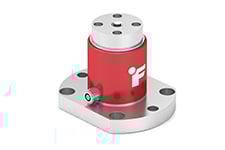
Flange-to-Flange Thru Hole Reaction Torque Sensor
Flange-to-Square-Drive Torque Sensor
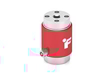
Square-Drive to Square-Drive Reaction Torque Sensor
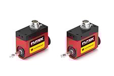
Shaft-to-Shaft Reaction Torque Sensor
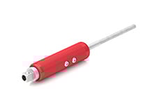
Screw Driver Torque Sensor
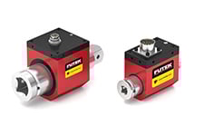
Shaft-to-Shaft Rotary Torque Sensor with Encoder
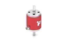
Square Drive Rotary Torque Sensor
Male/Female Hex-Drive Rotary Torque Sensor
Custom Torque Sensor
Torque Sensors manufactured in US by FUTEK Advanced Sensor Technology (FUTEK), a leading manufacturer producing a huge selection of Torque Transducers, utilizing one of the most advanced technologies in the Sensor Industry: Metal foil strain gauge technology. It is is defined as a transducer used for torque measurement (aka torque sensing) that converts an input mechanical torque into an electrical output signal. Torsions Sensors are also commonly known as Torque Transducer, Torque Cell or Moment Sensor. There are two main types of Torque Sensors: Reaction Torque Sensors or Rotational Torque Sensors.