Torque Sensor Selection | Torque Sensor Sizing | FUTEK
Important Considerations in Selecting a Torque Sensor
Last month, we began the first of a three part series on the critical factors you should consider when you are selecting a Load Cell, Torque Sensor or Pressure Sensor. We covered the guidelines for a Load Cell selection so now we move onto Torque Sensors. Before we do though, we shall emphasize that you need to take the proper steps to qualify the right company. It is very important to find a sensor provider that has the experience to support your needs and the know-how to provide the optimized solution. Find out if the company has worked with similar applications in the past. If it is a completely new application in which there is no precedence, select a company that is known for taking on these new challenges and would be able to work with you every step of the way from design to manufacturing and implementation. If you require a nonstandard product, keep in mind that your expected delivery time and cost will be based on the complexity of the requirement.
Step 1
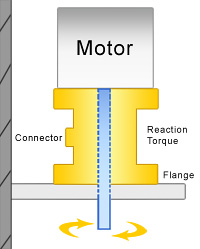
Understanding your application and defining your requirements are a crucial part of torque sensor sizing. What is reaction torque and how to measure motor torque using reaction torque sensor? After you’ve clearly defined your application, define what it is you want to measure, control or monitor. Do you want to measure torque? Meaning, do you want to convert a torsional mechanical input into an electrical output signal? Application examples include:
- Dynamometers
- Tool dulling indicator
- Motor control
- Inline rotating shaft feedback
- Monitoring mixer torque to meet required viscosity
- Integrated servomotor or stepping motor for further automation, feed back control and verifying regulated torque in frictionless bearings and long guide wires in medical application
- Torque wrench verification and/or calibration
Step 2
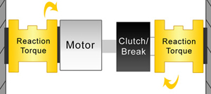
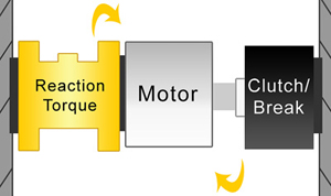
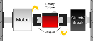
After you’ve determined that you want to measure torque, define the type of torque you want to measure – reaction torque or rotary torque. Reaction Torque Sensors have no moving parts so they pick up the reaction torque through your system. In the illustrations below you can see where the Rotary Torque Sensor would be used versus a Reaction Torque Sensor in an application involving a motor and break/clutch. Also be sure to define your size requirements (width, height, length, etc) and specification requirements (output, nonlinearity, hysteresis, creep, bridge resistance, temperature range, submersible, environment etc.)


Step 3
How will you be mounting the sensor? (Flange to flange, square drive, shaft to shaft, hex drive, etc.) Will you be using this clockwise, counterclockwise, or both? Similar to selecting a Load Cell, be sure to select the capacity over the maximum operating torque and determine all extraneous torque and over hung moments, off center prior to selecting the capacity. Note: extraneous torque and moments increase combined stress which will accelerate the fatigue and can affect the performance and accuracy if the correct Torque Sensor / transducer is not selected. For Rotary Torque Sensors you must also specify RPM and seek the assistance of tech support in for proper selection of Slip-Ring or non-contact type. You may also require sensor with built-in encoder for measuring speed and angular deflection or position.
Step 4
If you need an instrument for your application, select the instrument the same time you select the Torque Sensor. This will help you avoid non-compatibility. Also make sure the instrument sampling rate is sufficient to capture all torque changes at given RPM or break-away torque. Don’t forget to purchase system calibration with your order. This integrates your sensor and instrument as one system with NIST traceable certificate per ISO 17025, if required.