When measuring force in real world applications, electronics bridge the gap between mechanical systems and digital devices. Strain gauge-based sensors measure and convert physical quantities such as force into measurable electrical signals. In order for this data to be read, the sensor needs to be interfaced with a data acquisition system (DAQ or PLC) without losing meaningful information in the process. Signal conditioners and amplifiers help with this conversion. To understand their operation and use, a basic grasp of the physics underlying the gauge’s functioning is helpful. For a concise primer, see Force-Transducers.
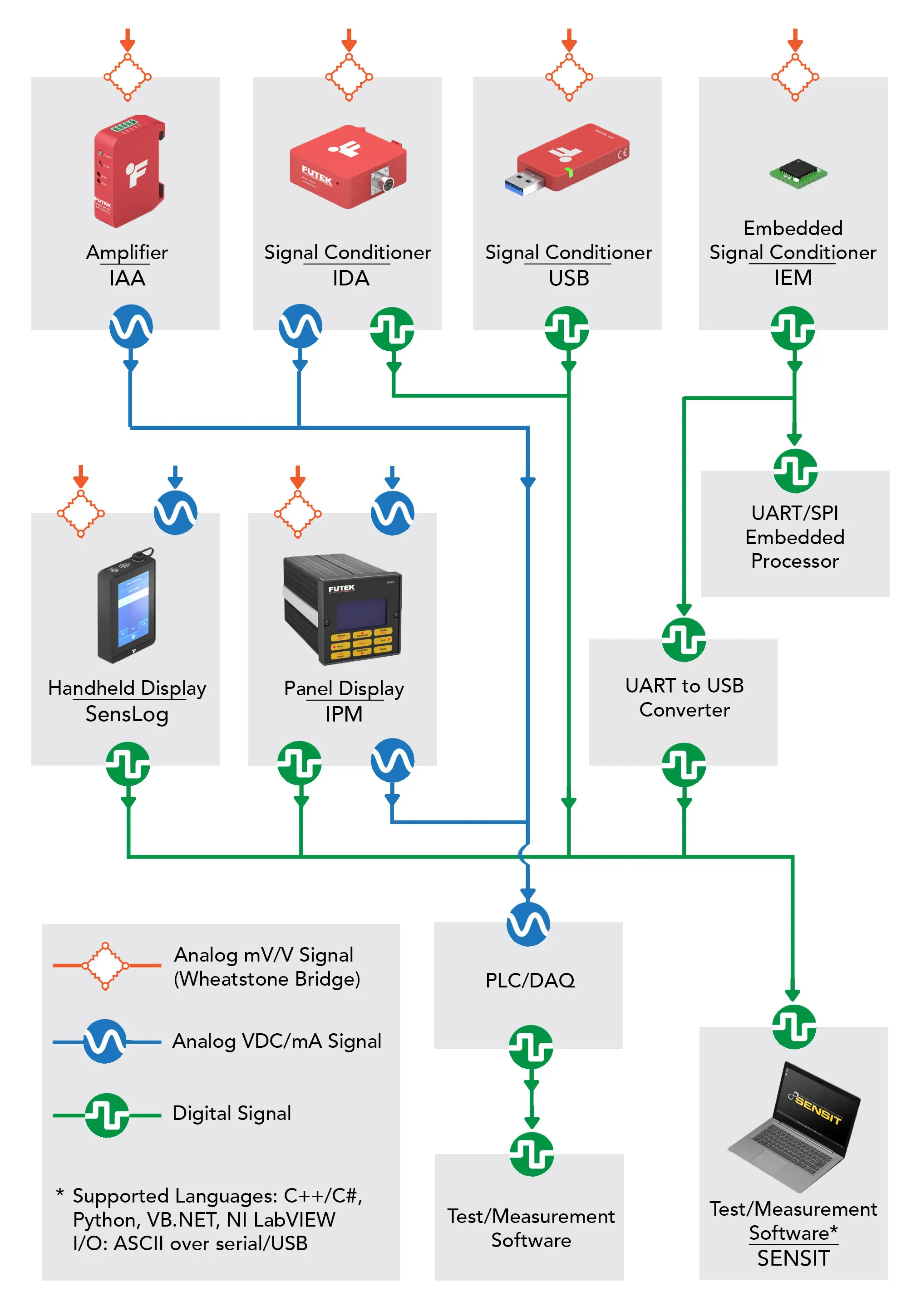
FUTEK provides high-performance electronics for signal amplification, digitization, and display, engineered specifically for strain-gauge (Wheatstone bridge) sensors. These signal-conditioners and amplifiers capture and convert low-level mV/V signals with high precision and are platform agnostic, integrating seamlessly with PLCs, DAQs, PCs, or custom embedded systems.
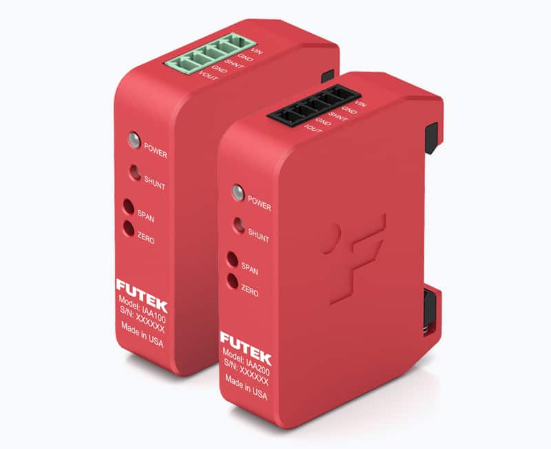
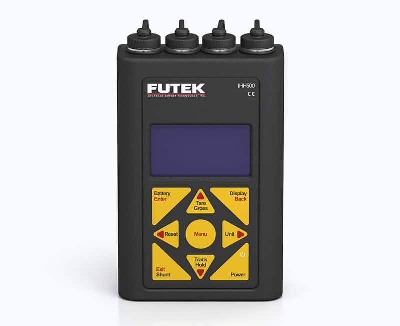
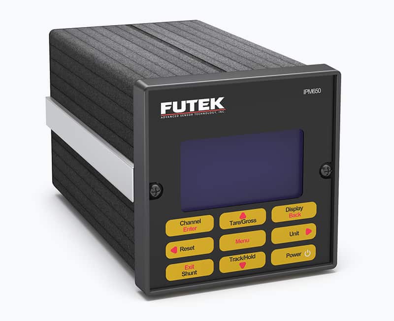
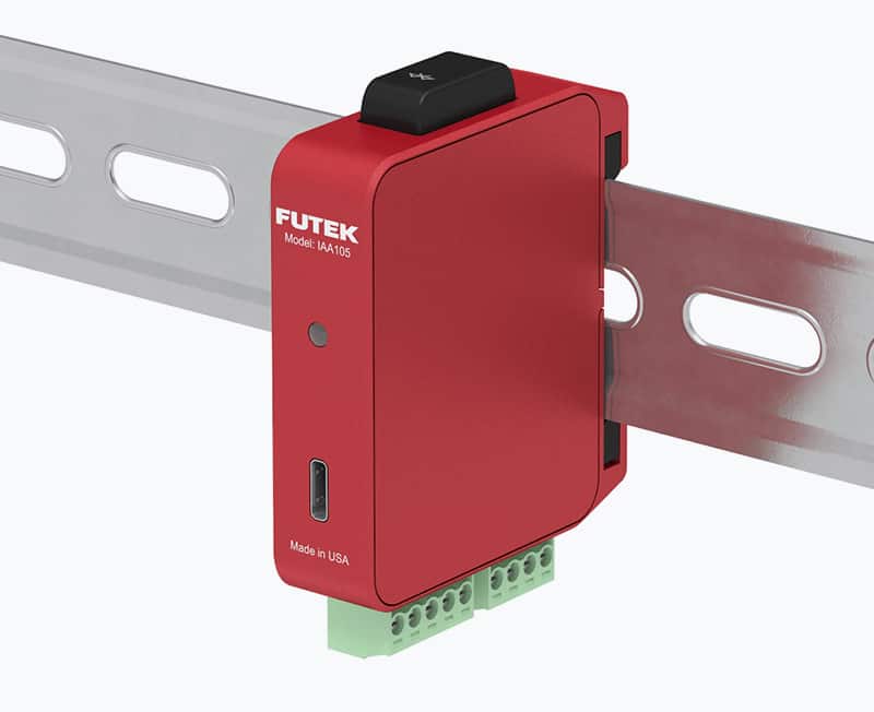
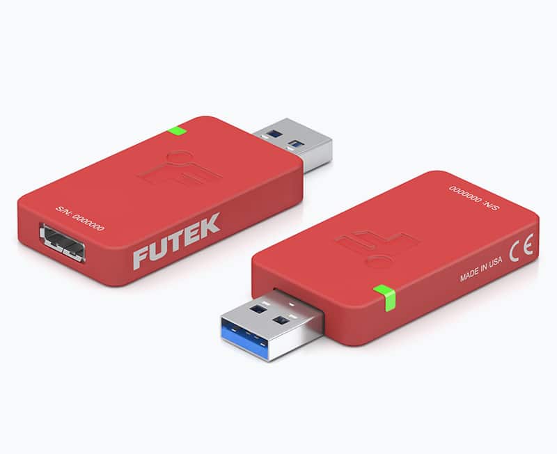
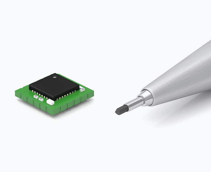
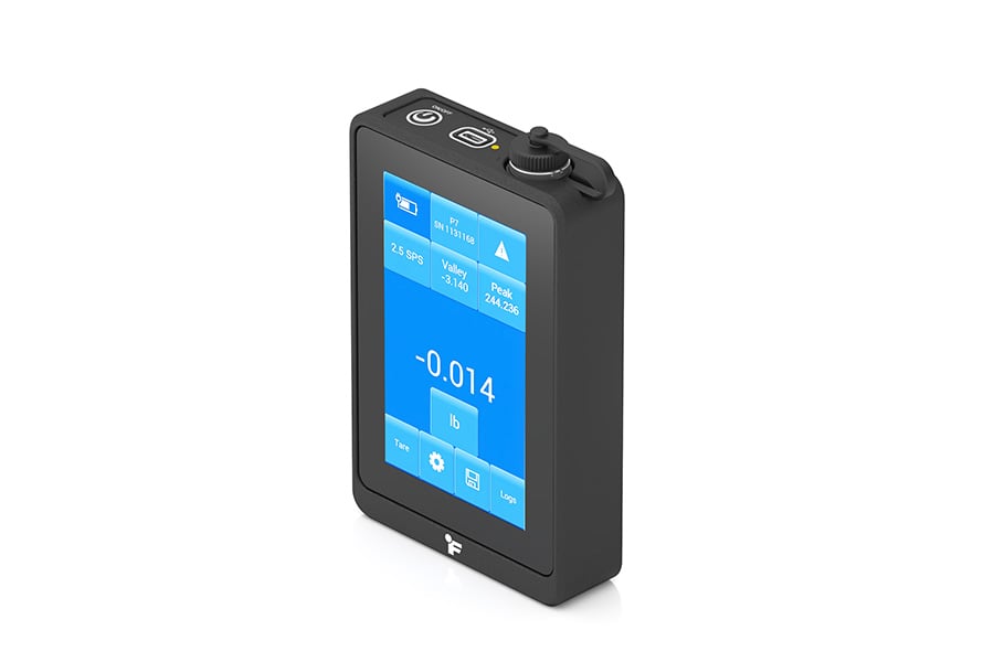
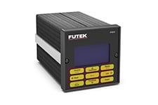
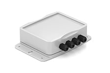
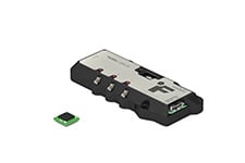
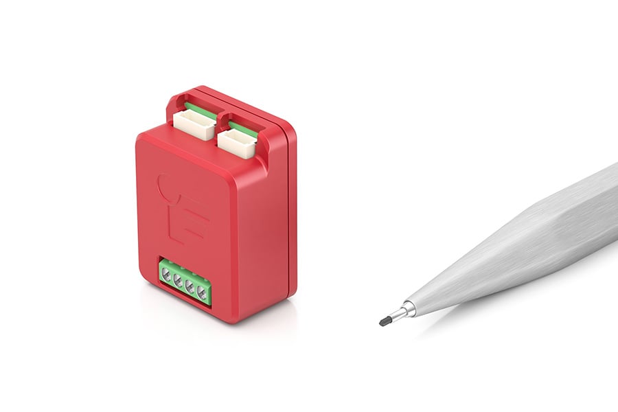
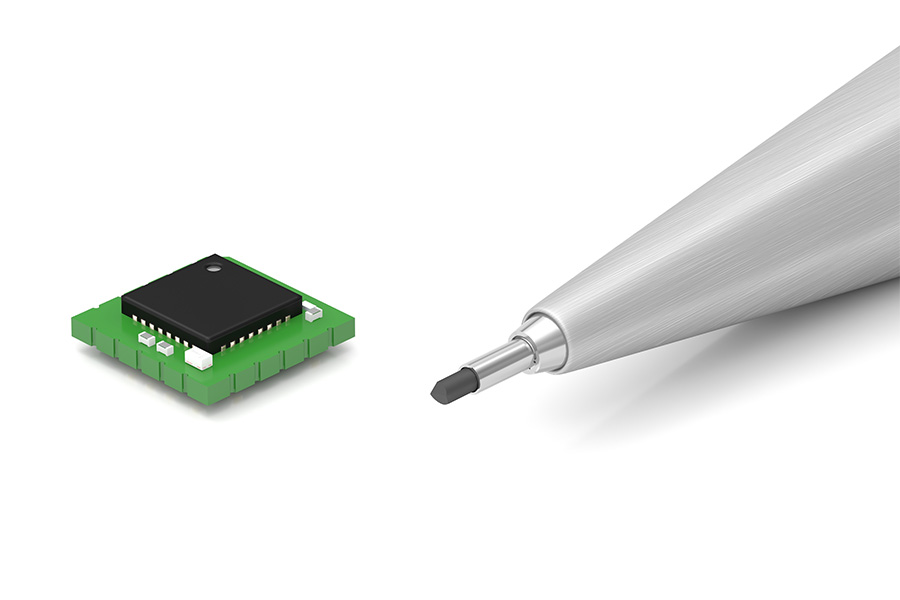
Offered in rack-mounted, portable, standalone, and embedded configurations, FUTEK’s versatile portfolio includes analog amplifiers, digital signal conditioners, USB modules, SPI/UART integrations, handheld displays, and OEM solutions. These electronics bridge the gap between mechanical sensing and digital control, making them ideal for industrial automation, aerospace, medical, and automotive applications.
Beyond amplification and filtering, FUTEK’s signal conditioners also help mitigate noise, drift, grounding and EMI that can distort sensor output. For a brief overview of these factors and to learn more about common features and capabilities, see Signal-Conditioners.
FUTEK’s electronics support a wide range of full-bridge strain gauge-based sensors across force, torque, pressure, and multi-axis applications. The choice of electronics depends on the setup and performance requirements of your application. Some of our most trusted models are highlighted below: