Supportkeyboard_arrow_right

Force Measurement

What is a force measurement sensor, what are the different types of sensors and how do they work?

Get to know the functionalities and capabilities of various load cells, also known as force transducers, in this comprehensive guide.


What is a Force Measurement Sensor?

A force sensor, also known as a load cell sensor, is a type of transducer, specifically a force transducer. It converts an input mechanical force such as load, weight, tension, compression or pressure into another physical variable. In this case, it is converted into an electrical output signal that can be measured, converted and standardized. As the force applied to the force sensor increases, the electrical signal changes proportionally. There are a large variety of load cell types based on size, geometry and capacity. Many of them are manufactured in the US by FUTEK Advanced Sensor Technology, a leading load cell manufacturer that utilizes one of the most advanced technologies in the sensor industry: metal foil strain gauge technology.

Force Transducers have become an essential element in many industries from automotive; high precision manufacturing; aerospace and defense; industrial automation; medical and pharmaceuticals, 3D Printing, and robotics, where reliable and high precision measurement is paramount. Most recently, rapid advancements in the fields of collaborative robots (cobots) and surgical robotics have given rise to many novel force measurement applications.

Check out our Force Sensors Store. More than 600+ types of force sensors available!


How does a force measurement sensor work?

Firstly, we need to understand the underlying physics and material science behind the strain force measurement working principle, which is the strain gauge (sometimes referred to as Strain gage). Strain gauges are electrical conductors tightly attached to a film in a zigzag shape. When this film is pulled, it — and the conductors — stretches and elongates. When it is pushed, it is contracted and gets shorter. This change in shape causes the resistance in the electrical conductors to also change. The strain applied in the load cell can be determined based on this principle, as strain gauge resistance increases with applied strain and diminishes with contraction.


force transducer strain gauge load cell
Fig 1: Metal Foil Strain gage. Source: ScienceDirect


Structurally, a force sensor load cell is made of a metal body (also called flexure) to which foil strain gauges are bonded. The sensor body is usually made of aluminum or stainless steel, which gives the sensor two important characteristics: (1) provides the sturdiness to withstand high loads and (2) has the elasticity to minimally deform and return to its original shape when the force is removed.


When force (tension or compression) is applied, the metal body acts as a “spring” and is slightly deformed, and unless it is overloaded, it returns to its original shape. As the flexure deforms, the strain gauge also changes its shape and consequently its electrical resistance, which creates a differential voltage variation through a Wheatstone Bridge circuit. Thus, the change in voltage is proportional to the physical force applied to the flexure, which can be calculated via the load cell circuit voltage output.

Fig. 2: Strain gauge deformation in both tension and compression.


Check out our Force Sensors Store. More than 600+ types of force sensors available!


These strain gauges are arranged in what is called a Wheatstone Bridge Circuit (see animated diagram). This means that four strain gages are interconnected as a loop circuit (load cell circuit) and the measuring grid of the force being measured is aligned accordingly.


The strain gauge bridge amplifiers (or load cell signal conditioners) provide regulated excitation voltage to the load cell circuit and convert the mv/V output signal into another form of signal that is more useful to the user. The signal generated by the strain gage bridge is low strength signal and may not work with other components of the system, such as PLC, strain gauge data acquisition system (strain gauge DAQ), computers, or microprocessors. If the PLC does not come with a special strain gauge I/O card, it needs a strain gauge module

That being said, force sensor signal conditioners' functionalities include excitation voltage, noise filtering or attenuation, signal amplification, and output signal conversion.


Furthermore, the change in the amplifier voltage output is calibrated to be linearly proportional to the Newtonian force applied to the flexure, which can be calculated via the load cell circuit voltage equation.

Fig. 3: Strain Gauge Force Sensor Circuit – Full Bridge Wheatstone Circuit.


Check out our Force Sensors Store. More than 600+ types of force sensors available!


An important concept regarding force transducers is force sensor sensitivity and accuracy. Force sensor accuracy can be defined as the smallest amount of force that can be applied to the sensor body required to cause a linear and repeatable variation in the voltage output. The higher the load cell accuracy, the better, as it can consistently capture very sensitive force variations. In applications like high precision factory automation, surgical robotics, space grade sensors, load cell linearity is paramount in order to accurately feed the PLC or DAQ control system with accurate measurement. Some of our universal pancake load cells present nonlinearity of ±0.1% (of Rated Output) and non-repeatability of ±0.05% RO.


What are the advantages of strain gauge-based sensors?

Metal foil strain gauge force sensors are the most common technology, given its high accuracy, long term reliability, variety of shapes and sensor geometry and cost-effectiveness when compared to other measurement technologies. Also, strain gage sensors are less affected by temperature variations.

  • The highest accuracy which may conform to many standards from Surgical Robotics to Aerospace;
  • Robust Construction made of either high strength Stainless steel or Aluminum;
  • Maintain high performance at the longest possible work life even at the most rigorous conditions. Some load cell designs can go up to billions of fully reversed cycles (lifespan).
  • A plethora of geometries and customized shapes, as well as mounting options for ANY scale ANY-where.
  • A full gamut of selections with capacities ranging from 10 grams to 100,000 pounds.


What are the types of strain gage-based sensors?

Although there several technologies to measuring force, we will focus on the most common type of load cell: metal foil strain gauge. Within the types of force sensors, there are a variety of body shapes and geometries, each one catering to distinct applications. Get to know them if you want to buy load cell:


How to choose a force measurement sensors for your application?

We understand that choosing the right load transducer is a daunting task, as there is no real industry standard on how you go about selecting a load cell for sale. There are also some challenges you may encounter, including finding the compatible amplifier or signal conditioner or requiring a custom product that would increase the product’s delivery time.

To help you select your force sensor, FUTEK developed an easy to follow, 5-Steps guide. Here is a glimpse to help you narrow down your choices. Check out our “Important Considerations in Selecting a force measurement sensor” complete guide for further information.

  • Step 1: Understand your application and what you are measuring. A Load sensor is different from pressure sensor, torque sensor or force torque sensor and they are designed to measure tension and compression loads.
  • Step 2: Define the sensor mounting characteristics and its assembly. Do you have static load or is it a dynamic type? Define the mounting type. How will you be mounting this Force Sensor?


In-Line Diagram load cell sizing how to select a load cell
In-Line Diagrams
Side Mount Diagram load cell sizing how to select a load cell

Side Mount Diagram load cell sizing how to select a load cell
Side Mount Diagrams
  • Step 3: Define your minimum and maximum capacity requirements. Be sure to select the capacity over the maximum operating load and determine all extraneous load (side loads or off-center loads) and moments prior to selecting the capacity.
  • Step 4: Define your size and geometry requirements (width, weight, height, length, etc) and mechanical performance requirements (output, nonlinearity, hysteresis, creep, bridge resistance, resolution, frequency response etc.) Other characteristics to consider include submersible (waterproof), cryogenic, high temperature, multiple or redundant bridges, and TEDS IEEE1451.4.
  • Step 5: Define the type of output your application requires. Force transducer circuits outputs voltage in mV/V. So, if your PLC or DAQ requires analog output, digital load cell output or serial communication, you will certainly need a load cell amplifier or signal conditioner. Make sure to select the right amplifier as well as calibrate the entire measurement system (load transducer + signal conditioner). This turnkey solution translates into more compatibility and accuracy of the entire force measurement system.

For more details on our 5-Steps Guide, please visit our “How to choose a Force Measurement Sensor” for complete guidelines.


Check out our Force Sensors Store. More than 600+ types of force sensors available!


Why is it important to calibrate force sensors?

Force Sensor Calibration is an adjustment or set of corrections that are performed on a sensor, or instrument (amplifier), to make sure that the sensor operates as accurately, or error-free, as possible.

Every force transducer is prone to measurement errors. These structural uncertainties are the simply algebraic difference between the value that is indicated by the sensor output versus the actual value of the measured variable, or known reference forces. Measurement errors can be caused by many factors:

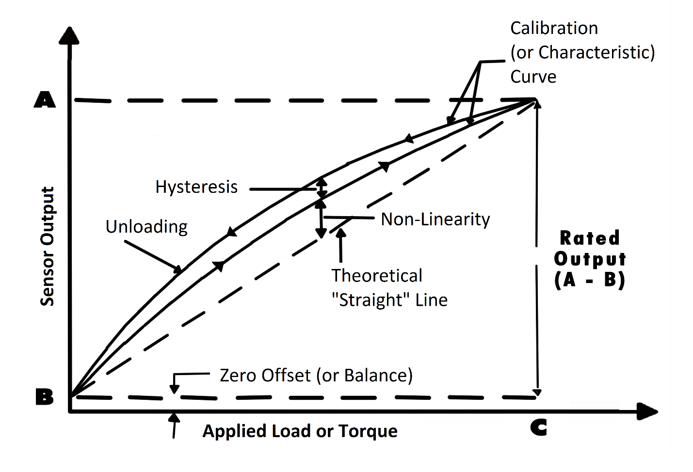
Zero offset (or force sensor zero balance): An offset means that the sensor output at zero force (true zero) is higher or lower than the ideal output. Additionally, zero stability relates to the degree to which the transducer maintains its zero balance with all environmental conditions and other variables remaining constant.

Linearity (or non-linearity): Few sensors have a completely linear characteristic curve, meaning that the output sensitivity (slope) changes at a different rate throughout the measurement range. Some are linear enough over the desired range and does not deviate from the straight line (theoretical), but some sensors require more complex calculations to linearize the output. So, force sensor non-linearity is the maximum deviation of the actual calibration curve from an ideal straight line drawn between the no-pressure and rated pressure outputs, expressed as a percentage of the rated output.

Hysteresis: The maximum difference between transducer output readings for the same applied force; one reading is obtained by increasing the force from zero and the other by decreasing the force from the rated output. It usually measured at half rated output and expressed as a percentage of the rated output. Measurements should be taken as rapidly as possible to minimize creep.

Repeatability (or non-repeatability): The maximum difference between transducer output readings for repeated inputs under identical force and environmental conditions. It translates into the force transducer's ability to maintain consistent output when identical force are repeatedly applied.

Temperature Shift Span and Zero: The change in output and zero balance, respectively, due to a change in transducer temperature.

pressure transducer sensor calibration curve lab zero balance sensitivity pressure transducer calibration
Fig 5: Force Transducer Sensor Calibration Curve.

Each force sensor has a "characteristic curve" or a "calibration curve", which defines the sensor's response to an input. During a regular calibration using the force transducer calibration machine, we check the sensor's zero offset and linearity by comparing the sensor output under reference forces and adjusting the sensor response to an ideal linear output. The force sensor calibration equipment also check hysteresis, repeatability and temperature shift when customers request it for some critical force measurement applications.

For more information about calibration, please refer to our Sensor Calibration FAQ Page.

If you have further questions about calibration terms and definitions, please refer to our Sensor Calibration Terms Glossary.

Want to know what calibration services we offer for your sensor and/or system?

Contact us to learn more!


How often should a force measurement sensor be recalibrated?

As strain gauge force sensors are exposed to continuous usage, aging, output drift, overload and improper handling, FUTEK highly recommends a yearly recalibration interval. Frequent recalibration helps confirm whether the sensor maintained its accuracy over time and provides a load cell calibration certificate to show that the sensor still meets specifications.

However, when the sensor is used in critical applications and harsh environments, force sensors may require even more frequent calibrations. Please consult appropriate calibration intervals with our Technical Support team, who will help you evaluate the most economical calibration service interval for your force transducer.


Check out our Force Sensors Store. More than 600+ types of force sensors available!


Multi Axis Sensor, Force, Torqueforce-measurement
+
Z540-1 ANSI Certified17025 ISO Certified9001 ISO Certified13485 ISO CertifiedU.S. Manufacturer
+
Please follow us on linked inPlease follow us on twitterPlease follow us on youtubePlease Email us for additional info
+
10 Thomas, Irvine,
CA 92618 USA
All other trademarks, service marks and logos used in this website are the property of their respective owners.
© 1998–2024 FUTEK Advanced Sensor Technology, Inc. All rights reserved.