Electric Motor Output Power
Basic concepts of electric motor efficiency
Electric motors are electromechanical machines that convert electric energy into mechanical energy through a spinning shaft. Despite differences in size and type, most electric motors work based on the same basic principle: an electric current flowing through a wire coil in a magnetic field (stator) creates a force that rotates the coil (rotor), thus creating torque (spinning shaft).
In that scenario, the motor efficiency is a ratio of how well the motor converts electrical energy into mechanical energy and is calculated by dividing the electrical power fed into the motor by the mechanical power generated from the motor. Mechanical power output is then calculated based on the torque and angular speed, and electrical power input is calculated based on voltage and current supplied to the motor. Mechanical power output is always lower than the electrical power input, as energy is lost during the conversion process in various forms, such as heat, friction, ohmic losses, and noise.
Regardless of motor type, the described losses cannot be completely designed out. However, understanding motor efficiency losses matter because less efficient units lead to higher operating costs over the life of the motor.
Electric motor output power
As described above, electrical motors transform electrical energy into mechanical work. Two important variables determine the mechanical capabilities of a motor: angular speed and torque. Mechanical power output of the motor could be calculated by using the following formula:
Pmech = Pout = τ * ω
where
- Pout: output power, measured in watts (W);
- τ: torque, measured in Newton-meters (N•m) or foot-pounds (ft/lbs);
- ω: angular speed, measured in radians per second (rad/s).
It is easy to calculate angular speed if you know the rotational speed of the motor in rpm (Revolutions per minute):
ω = rpm * 2π / 60
where
- ω: angular speed, measured in radians per second (rad/s);
- rpm: rotational speed in revolutions per minute;
- π: mathematical constant pi (3.1415);
- 60: number of seconds in a minute.
The consumed electrical power of the motor is defined by the following equation:
Pelet = Pin = I * V
where
- Pin: input power, measured in watts (W);
- I: current, measured in amperes (A);
- V: applied voltage, measured in volts (V).
The efficiency of the motor is calculated as mechanical output power divided by electrical input power:
Motor Efficiency = Pmech / Pelet = Pout / Pin
If the motor has 100% efficiency all electrical power is converted to mechanical energy (Pin = Pout). However such motors do not exist. Even precision-made small industrial motors have a maximum efficiency of 50-60%.
How do you measure the power output of a motor?
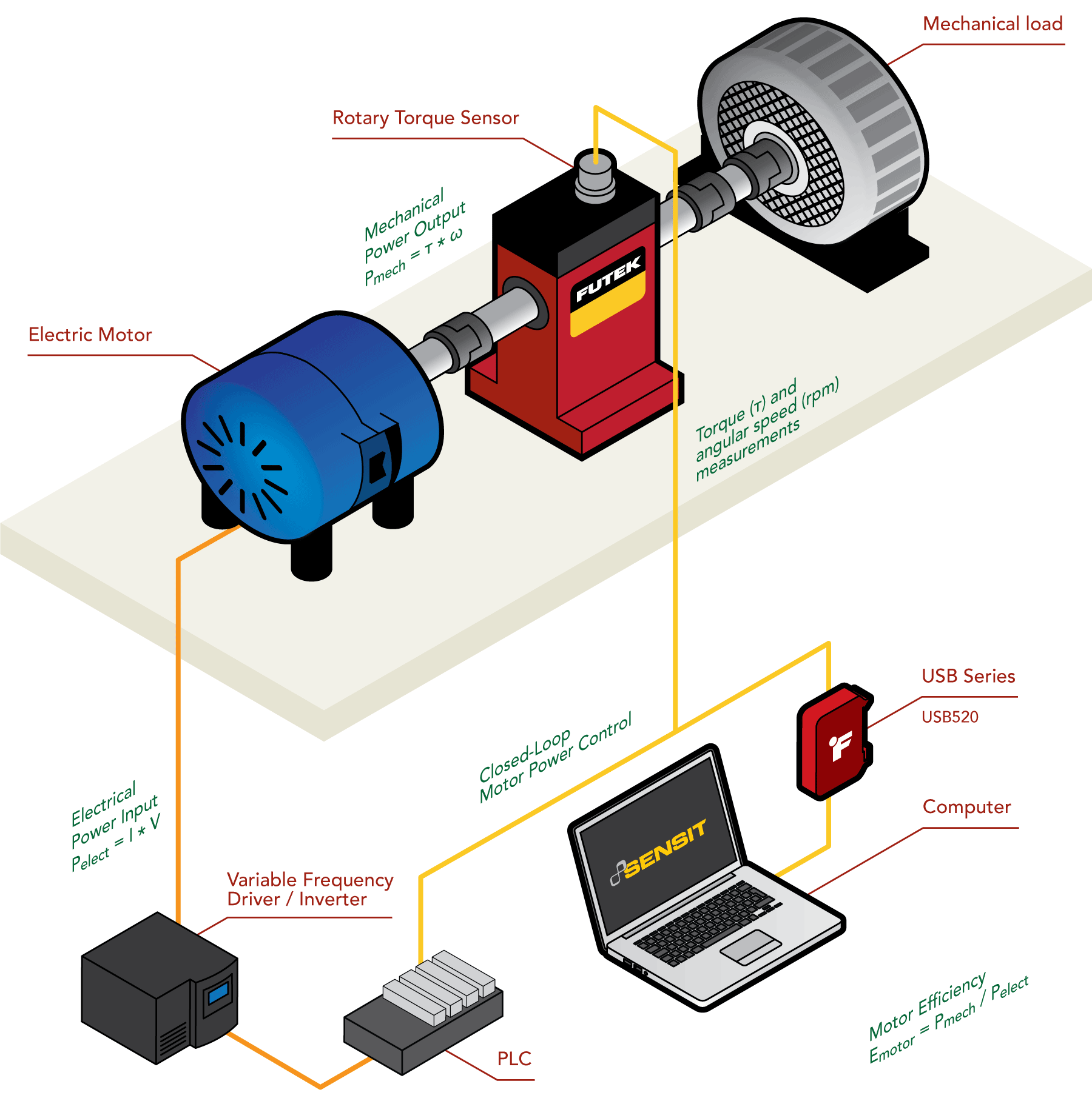
As detailed above, determining the power output of a motor requires measuring two variables simultaneously: torque and angular speed. For a precise and accurate torque and angular speed measurement, a rotary torque sensor with encoder paired with USB520 Universal Signal Conditioner is the recommended method. See the USB520 product brochure here for more information.
Rotary Torque Sensors
Rotary Torque Sensors are utilized in applications where the torque measurement must be taken at a spinning shaft. In this case, the transducer rotates in-line connected to the shaft. A rotary torque transducer is fitted with a slip ring or wireless electronics to transmit the torque signal while rotating.
The sensor is coupled between the motor and the mechanical load. As the shaft spins, the sensor measures the torque produced by the motor in response to the load applied to the rotating shaft. Some rotary torque sensors are equipped with built-in encoders. These encoders measure the angle/speed produced during the operation.
Watch the How does a Rotary Torque Sensor work? Webinar to learn more.
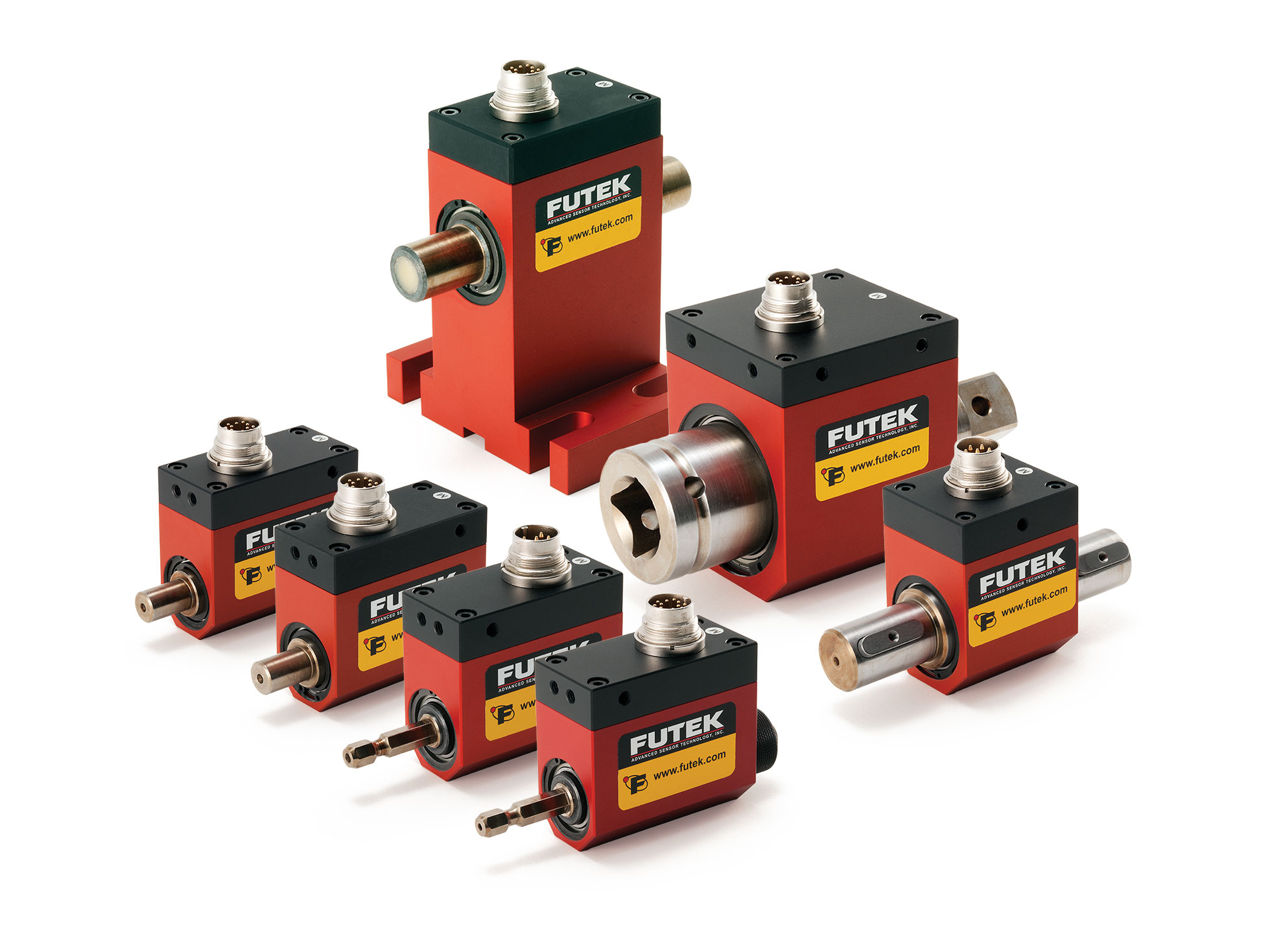
FUTEK Rotary Torque Sensors include an encoder that converts the angular motion or relative position of a shaft into pulse signals employing an optical disk. Encoders measures rotational or angular speed (RPM), thus allowing accurate calculation of the output power (Pout = τ * ω) and the motor efficiency.
FUTEK’s Rotary Torque Sensor with Encoder offers a unique solution for motor power auditing applications. The Rotary Torque Sensor with Encoder is available in a wide capacity range and utilizes strain gauge technology.
Rotary Torque Sensor Features
- Utilizes strain gauge technology for torque measurement
- Output Encoder to measure RPM and Angle;
- Compact size
- Can operate up to 7000 RPM
USB520 Universal Signal Conditioner
End-users can pair the USB520 Universal Signal Conditioner with any rotary torque sensor with encoder in the FUTEK product line for a turnkey, high-precision solution or can integrate it into any existing rotary torque application to improve data acquisition. It can monitor torque, speed, and power, as well as accept encoder measurements. It does not compromise speed, taking up to 4800 samplings per second (SPS), nor accuracy at ±0.005% of full-scale range (FSR).
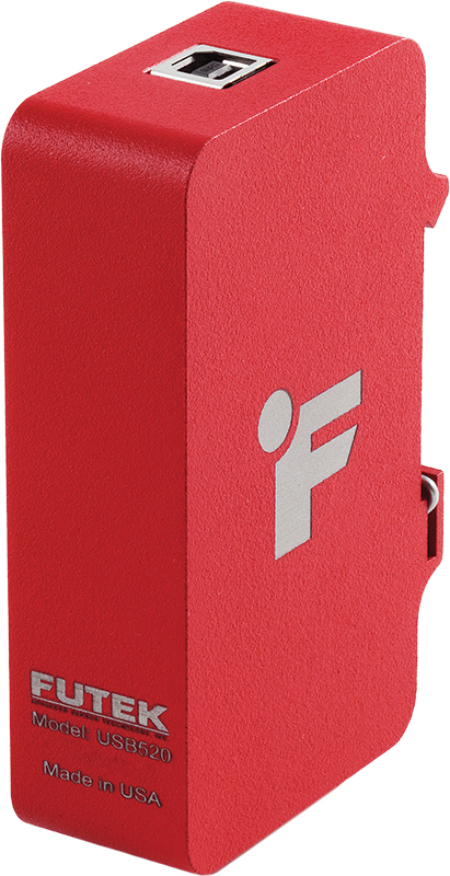
The USB520 can act as the power supply to the torque sensor within the allotted specifications of up to 24 VDC through the USB cable from the clean power source of the PC and can supply simultaneous 5 VDC to power an encoder. This eliminates the need for a power supply and benchtop or panel-mount equipment, which makes space constraints less of a challenge and allows a simple, plug-and-play connection to a PC for data acquisition.
In addition to power, the USB520 offers a solution that provides precise 4.6 VDC excitation while allowing the encoder to communicate digital data via its USB cable and 12-pin connector cable assembly. This cable provides the end to time-consuming wiring guides and countless stray wires. It provides pins for ± excitation, ± signal, supply output, ground, 5V output, ± voltage, and leading/lagging pulse.
The digitization of this USB solution significantly reduces the negatives of traditional platforms such as noise, low accuracy, temperature variation, and excitation. In fact, the resolution for the USB520 is uncompromised and noteworthy. At 5 SPS, users can experience 18.2 noise-free bits. At 4800 SPS, the resolution is rated at 13.9 noise-free bits making it a leader in its class. Its small size, integrated DIN rail clip, and aluminum enclosure are factors that contribute to convenience and durability in a rugged environment.
In addition to its three standard calibration profiles—mV/V, voltage, and current, the USB520 can save up to four different, customizable system calibrations locally on its internal memory. This feature allows multiple sensors to be paired with a single device, one at a time, giving the user the ability to choose the right sensor and profile for the right application. The seven calibration profiles that are available on the USB520 make it a cost-effective test and measurement solution.
USB520 Features
- Supports Encoder Input: Quadrature Leading and Lagging Pulse
- USB 2.0 Communication Link;
- USB Bus-Powered (5V);
- Input/Output Short Circuit Protection;
- Streaming ASCII Output;
- Offered with DLL/Mac Dynamic Library;
- CE Approved Class A (required for Medical and Aerospace applications);
- Industrial metallic enclosure;
- Integrated DIN rail mount;
- Supports, VDC, mA, mV and TTL type input;
- Review USB520 Encoder Rotary Torque Package brochure to learn more.