LVDT Signal Conditioning Module | FUTEK
What are the functions of an LVDT Signal Conditioning Module?
The function of an LVDT Signal Conditioning Module is to capture the signal from the displacement sensor and convert it into a higher level of an electrical signal. These electronic devices are also know as amplifiers, given it converts and modulates electrical signals. In order to do so, the sensor output goes through several different signal conditioning steps:
Excitation Voltage
Full-bridge LVDT sensors require an excitation voltage to feed the strain gage bridge and generate their output signal as a ratio of the input excitation voltage. Thus, you need to establish if your DAQ or PLC can support the sensor’s input voltage or excitation voltage requirements. Simply put, an unstable excitation voltage input leads to an unstable sensor output. In case you you need a LVDT amplifier module for PLC or DAQ and they do not provide a stable input excitation voltage, the amplifier will be the excitation voltage source to ensure the sensor provides a reliable and consistent output signal.
Filtering
Analog sensor signals are susceptible to electrical noise and/or residual ripple voltage, which can distort or skew measurements. Noise needs to be filtered out before you can capture an accurate signal. DAQs and PLCs designed to interface directly with full-bridge sensors will include pass band and other forms of signal conditioning and filtration. In a low noise signal conditioner, electronic filters eliminate some effects on accuracy by removing electrical noise and ripple effect above and below the analog sensor’s signal range, resulting in a high signal to noise ratio.
Amplification
Sensors can output a signal in the nanovolt through millivolt range. When your DAQ or PLC is limited to measuring volts, you will need an strain gage amplifier to convert millivolts to a larger signal. Some PLCs and DAQs come with built-in amplification; others will require an external amplifier. What if your existing DAQ or PLC does not provide built-in amplification, signal conditioning, and a stable power source for sensor excitation? In that case, you will need an amplifier to fill in the shortfalls in your instrumentation.
USB520 Universal Amplifier - Our Solution to LVDT Signal Conditioning
USB520 Universal LVDT Signal Conditioner Module supports a wide range of sensor inputs such as ± 10 VDC, 0-20 mA, ±400 mV/V and TTL encoder pulses type inputs. USB520 USB Universal Signal Conditioner Module can be paired with various sensor types and eliminates the need for external power supply to the sensor and display equipment. The module is supplied by PC power through the USB bus, providing excitation voltage selectable 5-24 VDC / 1W to the sensor and simultaneously 5 VDC for Encoder.
The sensor output is digitized up to 4,800 SPS and processed by a microprocessor using the integrated high resolution (24 bits) analog to digital converter (ADC). As it supports a wide range of sensor inputs such as ± 10 VDC, 0-20 mA, ±400 mV/V and TTL encoder type inputs, USB520 USB Digital Signal Conditioner can be paired with various sensor types, such as:
- String Pot Position Sensors (draw-wire sensor);
- Rotary Torque Sensors;
- DC LVDT Displacement Transducer;
- TTL Output Encoders to measure RPM and Angle;
The USB integration works hand in hand with SENSIT Test and Measurement software, which allows users to monitor the actual output of the sensor in real-time. FUTEK developed DLL Libraries to allow USB520 to also work with other software such as LabView® and Visual Studio.
USB520 Features
- USB 2.0 Communication Link;
- USB Bus-Powered (5V);
- Input/Output Short Circuit Protection;
- Streaming ASCII Output;
- Offered with DLL/Mac Dynamic Library;
- CE Approved Class A (required for Medical and Aerospace applications);
- Industrial metallic enclosure;
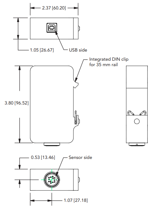
- Integrated DIN rail mount;
- Supports, VDC, mA, mV and TTL type input.
Dimensions
Specifications
| GENERAL | |
|---|---|
| Sampling Rate | Up to 4800 SPS |
| Bandwidth (Hz) | Sampling Rate (SPS) / 4 |
| Internal Resolution | 24 bits |
| Resolution (Noise Free) | See Chart on Page 3 |
| Non Linearity (max) | ± 0.005% of FSR |
| Output | Digital Packetized Data |
| Integrated Digital Filter | 50 Hz/60 Hz Rejection (100 dB) |
| On Chip Memory | 1 Kilobyte |
| Stored Calibration | Up to 16 Points |
| Weight | 0.43 lb (195 g) |
| On Chip Sensor Profiles | Up to 4 |
| ASCII Output Update Rate | 10 SPS |
| IP Rating | IP50 |
| ENCODER INPUT | |
| Encoder Input | Quadrature Leading and Lagging Pulse (TTL) |
| Speed Measurement | Up to 150k Pulses Per Second¹ |
| Angle Measurement (α) | Up to 10k Pulses Per Rotation (PPR)¹ |
| Angle/Speed Measurement (Update Rate) | 100 ms |
| STRAIN GAUGE mV/V INPUT | |
| Bridge Excitation | 4.6 VDC |
| Standard Input Range | ± 3.4 mV/V (factory default) |
| Optional Input Range | Up to ± 400 mV/V |
| Min. Bridge Resistance | 50 Ohm |
| Max. Bridge Resistance | 5000 Ohm |
| VOLTAGE INPUT | |
| Supply Voltage | Selectable 5,9,10,12,15,18,20,24 VDC/1W |
| Standard Input Range | ± 10 VDC (Factory Default) |
| CURRENT INPUT | |
| Supply Voltage | Selectable 5,9,10,12,15,18,20,24 VDC/1W |
| Standard Input Range | 0-20 mA (Factory Default) |
| CONNECTORS | |
| Sensor Connector | Binder 09 0132 90 12 |
| Mating Connector | Binder 99 5129 00 12 |
| USB 2.0 Connector | Type B |
| ¹ Speed = ∆ α × 60 / PPR | |
| ENVIRONMENT | |
| Operating Temperature | -13°F to 185°F [-25°C to 85°C] |
| Storage Temperature | -40°F to 257°F [-40°C to 125°C] |
| CONFORMITY | |
| RoHS | 2011/65/EU |
| CE | EN61326-1:2013; EN55011:2009 (Amended by A1:2010) |
| SAMPLES PER SECOND (SPS) | mV/V RESOLUTION | mA AND VDC INPUT RESOLUTION |
|---|---|---|
| 5 | 18 | 20.5 |
| 50 | 16.5 | 19.5 |
| 100 | 16.3 | 19.2 |
| 300 | 15.8 | 18.2 |
| 1200 | 14.6 | 17.0 |
| 2400 | 13.6 | 16.0 |
| 4800 | 13.6 | 16.0 |
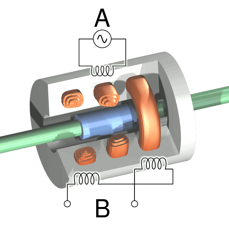
What is a Linear Variable Differential Transformer?
An LVDT is an electromechanical sensor used to transform mechanical motion into a variable electrical signal (current or voltage) and is used for measurement of displacement. They function as actuators for automatic control systems or as mechanical motion sensors in measurement technologies.
LVDT is an acronym for Linear Variable Differential Transformer. LVDT linear position sensors can measure displacements ranging from few microns to centimeters, but are also capable of measuring positions up to ±1 meter.
In short, a LVDT sensor provides output quantity in voltage or current, related to the displacement or movement being measured. LVDT Transducers are prone to external electromagnetic interference.
A linear displacement transducer requires three to four connection wires for power supply and output signal delivery.
Physically, the LVDT Transducer construction is a hollow metallic cylinder in which a shaft of smaller diameter moves freely back and forth along the cylinder's long axis. The shaft, or pushrod, ends in a magnetically conductive core which must be within the cylinder, or coil assembly, when the device is operating.
In common practice, the pushrod is physically attached to the moveable object whose position is to be determined (the measurand), while the coil assembly is attached to a fixed reference point. Movement of the measurand moves the core within the coil assembly; this motion is measured electrically.