Draw Wire Sensor | FUTEK
What is a Draw Wire Sensor?
A string potentiometer is a linear position sensor, also known as a string pot, draw wire position sensor, Cable Extension displacement transducer, or a yo-yo pot. It is a cable-actuated position or displacement transducer utilized for linear position measurement and velocity using a flexible cable (string) and a spring-loaded spool.
Draw wire sensors are low-cost, compact linear transducers that accurately measure the position, change in position, or velocity of objects.
Core elements of a String Potentiometer Transducer are a precision measuring wire and a sensor element (e.g. high precision potentiometer or encoder), which convert the wire linear displacement into a proportional electrical signal via the potentiometric voltage divider. The maintenance-free draw wires are particularly quick and easy to assemble and are used because of their reliability in all areas of industry.
String pots or cable-extension transducers are composed of four main components inside the housing:
- Flex High Strength Stainless Steel Cable (string or wire rope);
- Constant Diameter Spool (drum);
- High Torque, Long-life Power Coil Spring;
- Rotational Potentiometric Precision Sensor.
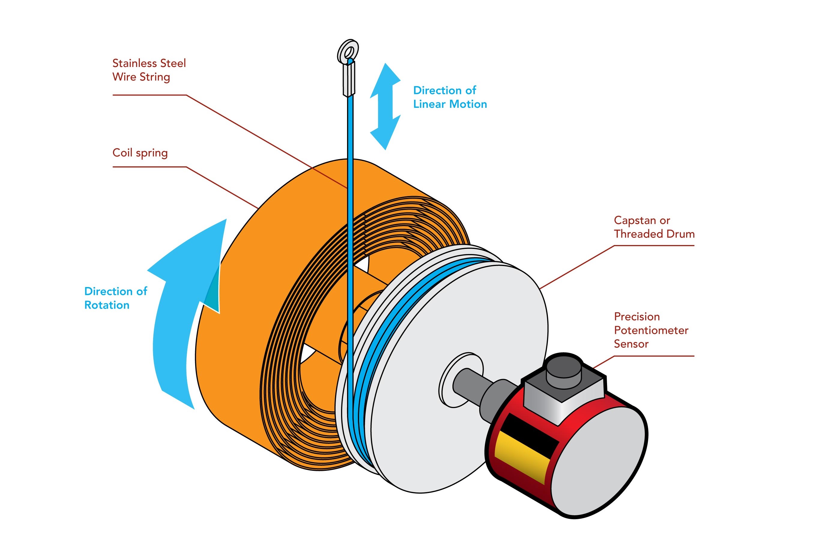
Inside the transducer's housing, a flexible high strength stainless steel cable is wound tightly around a precisely machined constant diameter cylindrical drum (or spool) that turns as the measuring cable reels and un-reels. To maintain wire tension and retraction, a spring is coupled to the drum. The spool is then coupled to the shaft of a rotational potentiometric precision sensor (or an encoder). As the sensor string extends linearly along with the moving object, it causes the drum and sensor shafts to rotate.
In order to take displacement or position measurements, the sensor’s body is mounted to a fixed surface and the end of the flexible cable is connected to the object in motion. As the object changes its positions, the cable un-reels and reels and the rotating spool drives the shaft of the sensing device generating an electrical signal that is proportional to the cable's linear extension or displacement. For speed measurement, a tachometer is required.
The draw wire displacement sensor can be hooked up as a three-wire tapped potentiometer (voltage divider) or can be packaged with embed electronics to produce an output signal in a useful form, such as a variable voltage 0-10 VDC, variable current 4-20mA, pulse encoder, Fieldbus (Profibus, DeviceNet, and Canbus) and RS232 / RS-485 communications. The sensor output signal can then be sent to a signal conditioner for amplification, local display or readout, a PLC or data acquisition system (DAQ).
Measuring the displacement and speed of moving objects is a simple task with draw wire sensors. String potentiometers have a very easy and intuitive installation and do not require a specialist to do so. Due to the flexibility and high strength of the cable, it can be fitted into precarious or tight areas and they do not require perfectly parallel alignment.
An obvious benefit of draw-wire measuring principle is that the measuring cable can be diverted over deflection pulleys. This characteristic differentiates string pot sensors from other linear displacement measurement principles which normally only measure on one axis. Moreover, as the sensor housings are is extremely compact, it enables large measuring ranges to be performed with a relatively very small transducer body, saving assembly space in your application.
String pots also offer great space flexibility as their housing size to measurement ratio it is higher than LVDT Linear Displacement Transducers, for example, and they normally are more cost-effective when compared to other linear position measurement technologies given the simplicity of the transducer operation.
Draw wire Transducers are selected for linear motion measurement as it presents the following advantages:
- Fast and easy assembly - can be installed in minutes without the need of an expert;
- Can fit into small spaces and relatively very good sensor size to measurement ratio - suitable for applications with constrained space or difficult to access locations;
- Given the flexibility of the wire rope, do not require perfect parallel alignment between the sensor body and the moving object to function accurately;
- Cost-effective linear displacement measurement option compared to alternatives;
- Suitable for displacement, distance, and position measurement from 25mm to 50,000 mm;
- High measurement resolution;
- High operational safety and extended service life;
- Analog and digital outputs.
Draw wire sensors are utilized to measure the position or displacement of a moving part. The measurement cable is attached directly to the moving object, giving a constant measurement of its linear position. This is a reliable position measurement technology and has proven to be effective by engineers and designers over the past four decades. String potentiometers are generally durable, simple to use, and inexpensive.
These sensors do not need precise linear guidance and are ideal for wet, dirty, or outdoor environments and applications where your measuring range travels through or hard-to-reach places. These include a broad variety of applications:
- factory automation and industrial machinery;
- medical devices and surgical robotics;
- structural civil engineering testing;
- automotive and aerospace testing;
- die-casting or injection molding;
- Telescopic applications
- oil and chemical;
- robotics;
- hydraulic cylinder position measurement and control
- just about anything moving object whose position is to measured.
Since the measuring cable may sag or be deflected by wind or gravity, the environmental conditions and orientation of the assembly must be considered in order to maintain the overall precision of a string potentiometer measurement.
The un-reel / reel cable-spool mechanism limits the speed at which the measured object can move. Changing temperatures affect both the length of the cable and the resistance value of the potentiometer, so additional temperature compensation devices must be employed in these scenarios.
Where multiple objects, such as articles on an assembly line, or objects that are hot or coated with wet paint are to be measured, a non-contacting method is preferred.
Other linear position measurement methods include LVDT, LVIT, strain-gages, potentiometric, capacitive, optical (time of flight), and magnetic-inductive transducers.
What are the functions of a Draw Wire Sensor Signal Conditioning Module?
The function of an Draw Wire Sensor Signal conditioner (aka draw wire sensor amplifier) is to capture the signal from the sensor and convert it into a higher level of electrical signal. These electronic devices are also known as amplifiers, given it converts and modulates electrical signals. In order to do so, the sensor output goes through several different signal conditioning steps:
Excitation Voltage
Full-bridge draw wire sensors require an excitation voltage to feed the strain gage bridge and generate their output signal as a ratio of the input excitation voltage. Thus, you need to establish if your DAQ or PLC can support the sensor’s input voltage or excitation voltage requirements. Simply put, an unstable excitation voltage input leads to an unstable sensor output. In case you you need a draw wire sensor amplifier module for PLC or DAQ and they do not provide a stable input excitation voltage, the amplifier will be the excitation voltage source to ensure the sensor provides a reliable and consistent output signal.
Filtering
Analog sensor signals are susceptible to electrical noise and/or residual ripple voltage, which can distort or skew measurements. Noise needs to be filtered out before you can capture an accurate signal. DAQs and PLCs designed to interface directly with full-bridge sensors will include pass band and other forms of signal conditioning and filtration. In a low noise signal conditioner, electronic filters eliminate some effects on accuracy by removing electrical noise and ripple effect above and below the analog sensor’s signal range, resulting in a high signal to noise ratio.
Amplification
Sensors can output a signal in the nanovolt through millivolt range. When your DAQ or PLC is limited to measuring volts, you will need an strain gage amplifier to convert millivolts to a larger signal. Some PLCs and DAQs come with built-in amplification; others will require an external amplifier. What if your existing DAQ or PLC does not provide built-in amplification, signal conditioning, and a stable power source for sensor excitation? In that case, you will need an amplifier to fill in the shortfalls in your instrumentation.
USB520 Universal Amplifier - Our Solution to Draw Wire Sensor Signal Conditioning
USB520 Universal Signal Conditioner Module supports a wide range of sensor inputs such as ± 10 VDC, 0-20 mA, ±400 mV/V and TTL encoder pulses type inputs. USB520 USB Universal Signal Conditioner Module can be paired with various sensor types and eliminates the need for external power supply to the sensor and display equipment. The module is supplied by PC power through the USB bus, providing excitation voltage selectable 5-24 VDC / 1W to the sensor and simultaneously 5 VDC for Encoder.
The sensor output is digitized up to 4,800 SPS and processed by a microprocessor using the integrated high resolution (24 bits) analog to digital converter (ADC). As it supports a wide range of sensor inputs such as ± 10 VDC, 0-20 mA, ±400 mV/V and TTL encoder type inputs, USB520 USB Digital Signal Conditioner can be paired with various sensor types, such as:
- String Pot Position Sensors (draw wire sensor);
- Rotary Torque Sensors;
- DC LVDT Displacement Transducer;
- TTL Output Encoders to measure RPM and Angle;
The USB integration works hand in hand with SENSIT Test and Measurement software, which allows users to monitor the actual output of the sensor in real-time. FUTEK developed DLL Libraries to allow USB520 to also work with other software such as LabView® and Visual Studio.
USB520 Features
- USB 2.0 Communication Link;
- USB Bus-Powered (5V);
- Input/Output Short Circuit Protection;
- Streaming ASCII Output;
- Offered with DLL/Mac Dynamic Library;
- CE Approved Class A (required for Medical and Aerospace applications);
- Industrial metallic enclosure;
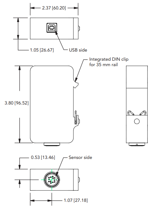
- Integrated DIN rail mount;
- Supports, VDC, mA, mV and TTL type input.
Dimensions
Contact Us
Specifications
| GENERAL | |
|---|---|
| Sampling Rate | Up to 4800 SPS |
| Bandwidth (Hz) | Sampling Rate (SPS) / 4 |
| Internal Resolution | 24 bits |
| Resolution (Noise Free) | See Chart on Page 3 |
| Non Linearity (max) | ± 0.005% of FSR |
| Output | Digital Packetized Data |
| Integrated Digital Filter | 50 Hz/60 Hz Rejection (100 dB) |
| On Chip Memory | 1 Kilobyte |
| Stored Calibration | Up to 16 Points |
| Weight | 0.43 lb (195 g) |
| On Chip Sensor Profiles | Up to 4 |
| ASCII Output Update Rate | 10 SPS |
| IP Rating | IP50 |
| ENCODER INPUT | |
| Encoder Input | Quadrature Leading and Lagging Pulse (TTL) |
| Speed Measurement | Up to 150k Pulses Per Second¹ |
| Angle Measurement (α) | Up to 10k Pulses Per Rotation (PPR)¹ |
| Angle/Speed Measurement (Update Rate) | 100 ms |
| STRAIN GAUGE mV/V INPUT | |
| Bridge Excitation | 4.6 VDC |
| Standard Input Range | ± 3.4 mV/V (factory default) |
| Optional Input Range | Up to ± 400 mV/V |
| Min. Bridge Resistance | 50 Ohm |
| Max. Bridge Resistance | 5000 Ohm |
| VOLTAGE INPUT | |
| Supply Voltage | Selectable 5,9,10,12,15,18,20,24 VDC/1W |
| Standard Input Range | ± 10 VDC (Factory Default) |
| CURRENT INPUT | |
| Supply Voltage | Selectable 5,9,10,12,15,18,20,24 VDC/1W |
| Standard Input Range | 0-20 mA (Factory Default) |
| CONNECTORS | |
| Sensor Connector | Binder 09 0132 90 12 |
| Mating Connector | Binder 99 5129 00 12 |
| USB 2.0 Connector | Type B |
| ¹ Speed = ∆ α × 60 / PPR | |
| ENVIRONMENT | |
| Operating Temperature | -13°F to 185°F [-25°C to 85°C] |
| Storage Temperature | -40°F to 257°F [-40°C to 125°C] |
| CONFORMITY | |
| RoHS | 2011/65/EU |
| CE | EN61326-1:2013; EN55011:2009 (Amended by A1:2010) |
| SAMPLES PER SECOND (SPS) | mV/V RESOLUTION | mA AND VDC INPUT RESOLUTION |
|---|---|---|
| 5 | 18 | 20.5 |
| 50 | 16.5 | 19.5 |
| 100 | 16.3 | 19.2 |
| 300 | 15.8 | 18.2 |
| 1200 | 14.6 | 17.0 |
| 2400 | 13.6 | 16.0 |
| 4800 | 13.6 | 16.0 |