584 Products

The FUTEK load cells explainer

A foundational guide to understanding load cells/force sensors

FUTEK designs, develops, and manufactures a wide range of industry-leading load cell sensors using strain gauge technology. In this guide, you will learn the basics about these kinds of load cells; how they work, what types there are, and how to use them.

Understanding Force Measurement

Converting mechanical force

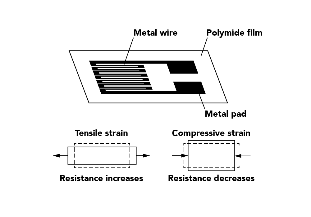
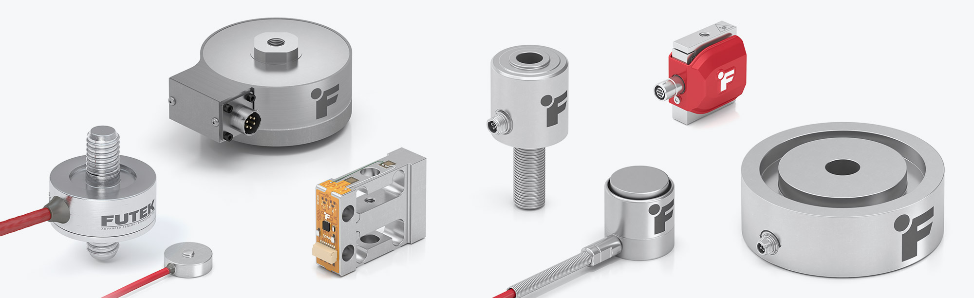
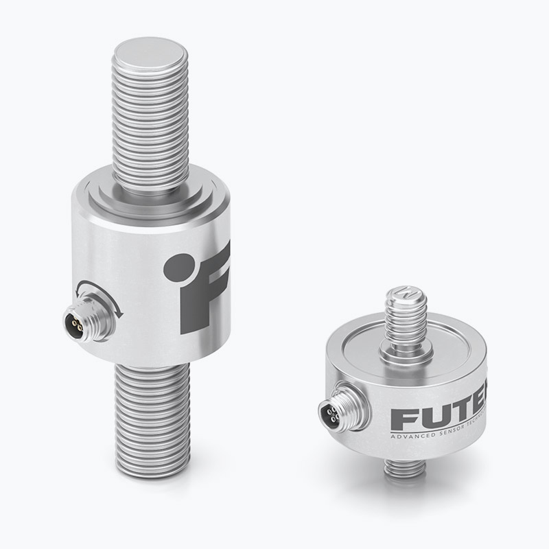
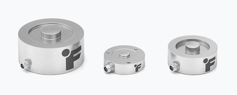
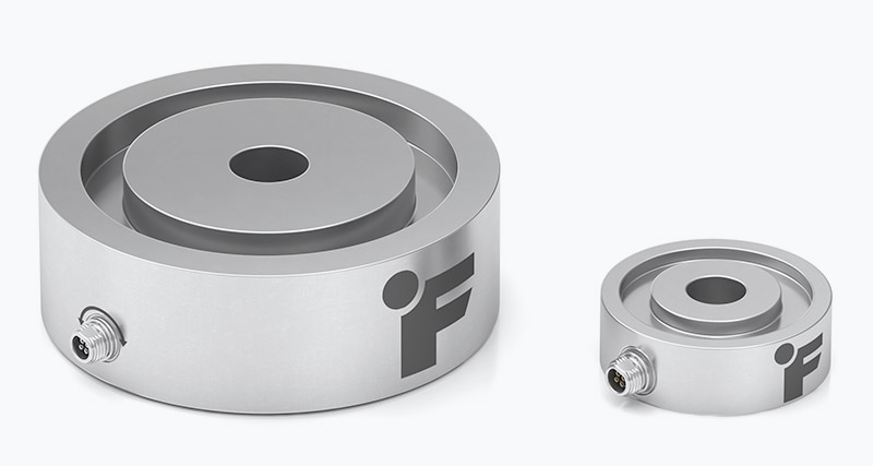
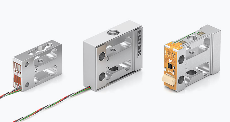
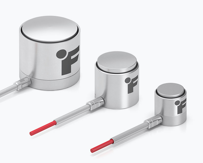
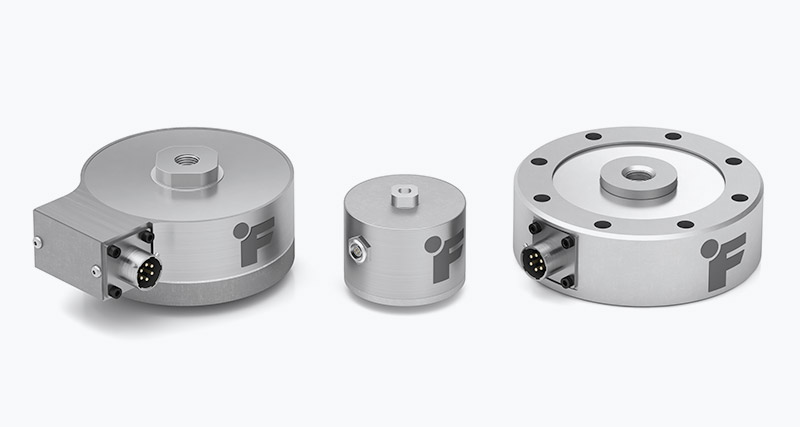
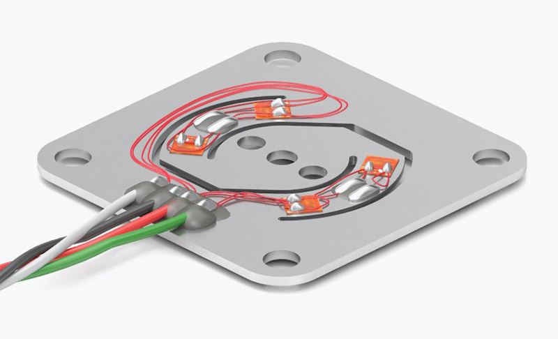
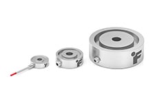
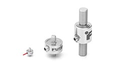
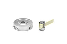
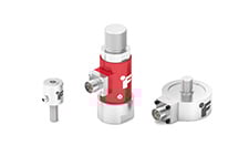
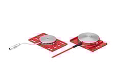
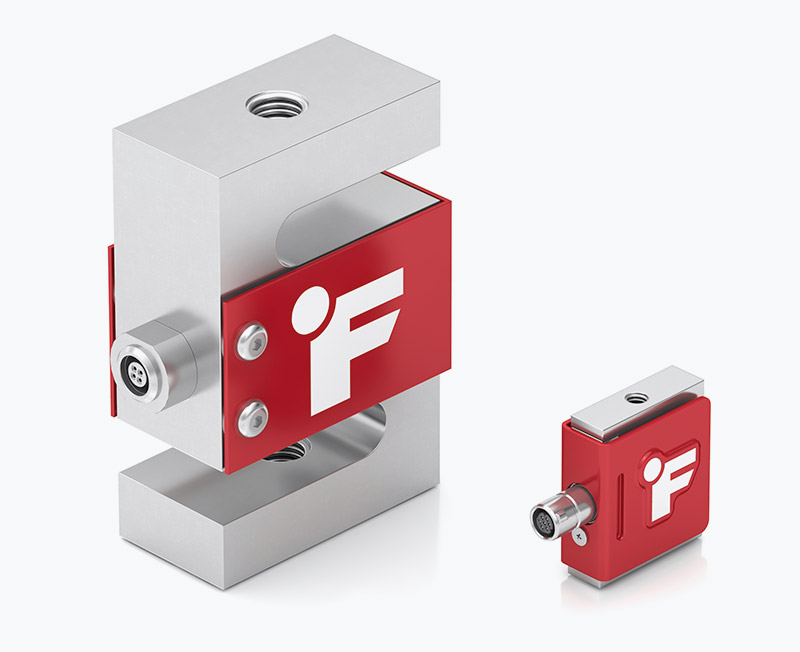
A load cell, which is also known as a force sensor or force transducer, is a sensor that measures force by converting the input of mechanical force into the output of an electrical signal. As the force is applied to the sensor, its electrical output signal can be measured, converted, and standardized. The input force can vary between load, weight, tension, compression, or pressure, and it can only be measured by a sensor that is designed to calculate that type of force. (We will break down the different kinds of load cells/ force transducers in the section below.)

Robotic Surgery Arm

Industries that use load cells

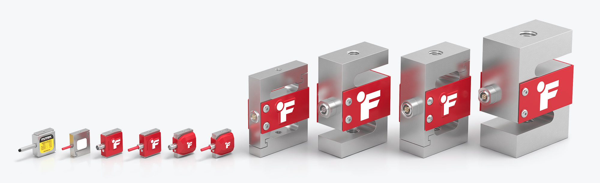
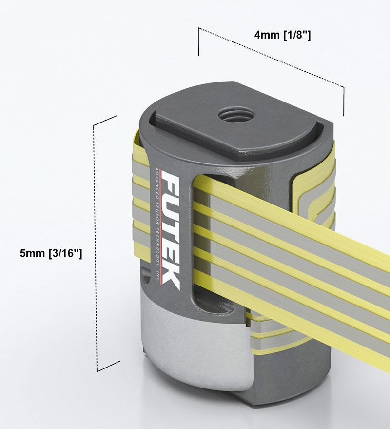
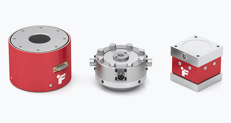
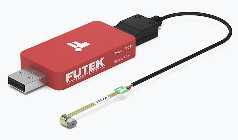
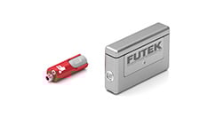
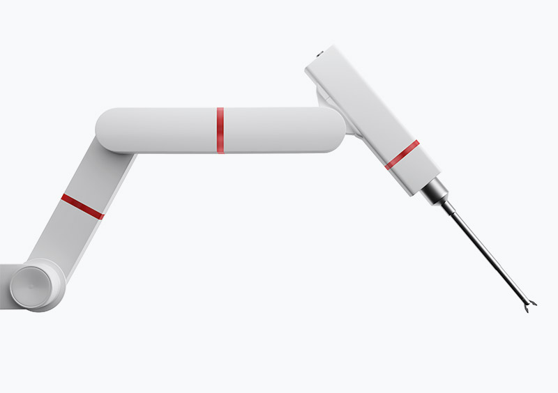
Due to their accuracy, load cells have become an essential element in many industries. Common sectors that rely on high-precision load measurement include automotive, high-precision manufacturing, aerospace and defense, industrial automation, medical and pharmaceuticals, and robotics. The design and development of load cell sensors are continuously evolving. With the current advancements in cobots and surgical robotics, many innovative force measurement applications are emerging, requiring ever more sophisticated force measurement solutions, such as FUTEK’s miniature medical sensors for robotic surgery.

Looking under the hood

Meet the strain gauge

The underlying physics and material science behind the force sensor working principle is tied to a component of the sensor that is called the strain gauge (or strain gage). Structurally, a load cell sensor is made of a metal body (also called flexure) to which foil strain gauges are bonded.

When stress is applied to a stationary object, the resulting deformation or displacement of its material causes strain that is captured by the strain gauge. Load cells and force sensors are designed to focus the stress (tension, compression, pressure, load) through elements where the strain gauges are located.

Anatomy of the strain gauge

Strain gauges are electrical conductors that are tightly attached to a film in a zigzag shape. When stress is transferred from the load cell flexure to the strain gauge, the resulting deformation or displacement of its material causes strain that ultimately is converted into the load cell’s measurable output. For example, when the film is pulled, it — and the conductors — stretches and elongates. When it is pushed, it is contracted and gets shorter. This change in shape causes the resistance in the electrical conductors, what we call strain gauge resistance, to also change. The strain gauge resistance increases with applied strain and diminishes with contraction. The changes are converted into an electrical signal, which can then be measured and captured using data acquisition.

Strain Gauge Diagram strain gage foil tension and compression

Understanding the Wheatstone bridge circuit

In order to measure the changes in resistance, the strain gauge must be connected to an electrical circuit that is capable of accurately responding to the changes and creating a differential voltage variation. Multiple strain gauges can be used in a divided bridge circuit that is called a Wheatstone bridge. In a Wheatstone bridge configuration, an excitation voltage is applied across the circuit, and the output voltage is measured across two points in the middle of the bridge. When there is no load acting on the load cell, the Wheatstone bridge is balanced and there is zero output voltage. Any small change in the material under the strain gauge results in a change in output.

The case for choosing FUTEK load cell sensors

In general, metal foil strain gauge load cell sensors are a popular measurement solution because of their durability and relatively low cost. In the case of FUTEK’s load cells, however, the most favored aspects are long-term reliability, variety of sizes and sensor geometry, and—most notably—high accuracy.

S-Beam Load Cell family

What is load cell accuracy?

One of the most important qualities of strain gauge load cells is load cell sensitivity and accuracy. Sensor accuracy can be defined as the smallest amount of force that can be applied to the sensor body required to cause a linear and repeatable variation in the voltage output. The higher the load cell accuracy, the better, as it can consistently capture very small force variations.

Proprietary strain gauge capabilities

FUTEK’s load cells feature an industry-leading metal foil strain gauge technology for its sensors. A highly customized strain element has been designed to allow more strain measurement around the active sensor element, which reduces reproducibility errors from off-axis loads. It also makes the sensor less sensitive to installation mishaps. Our proprietary foil strain gauges are encapsulated and feature internal compensation, ensuring long-term stability and improved reliability.

Nonlinearity and nonrepeatability

Load cell linearity is paramount to produce accurate output. FUTEK offers high precision load cells with as low as ±0.02% nonlinearity (of Rated Output) and nonrepeatability of ±0.02% RO, which make them adequate models for rocket engine thrust test stand applications.

Material matters

The body (or flexure) of FUTEK’s load cell sensors is made of aerospace-grade 17-4 stainless steel or aluminum. The high-quality materials provide sturdiness to withstand high loads as well as elasticity to minimally deform and return to its original shape when the force is removed. The exceptional quality also makes the force sensor highly durable and reliable with high strength, high hardness, low hysteresis and creep properties, and corrosion resistance over a wide temperature range.

Strain gauge-based load cells vs. Piezo load cells

The two most common types of load cells (or force sensors/force transducers) are Strain gauge load cells and piezoelectric load cells.

As we saw in the sections above, strain gauge-based load cells measure force via strain gauges that are connected in a Wheatstone bridge circuit. Piezoelectric sensors (or Piezo sensors) apply different mechanics to measure force. The unit has two crystal disks with an electrode foil mounted in between them. When force is applied, the friction between the disks and electrode results in an electrical charge that can be measured.

Piezoelectric sensors: compact package and high stiffness

Piezo sensors have high stiffness, which provides high natural frequency and a higher dynamic response and, because of their small components, Piezo force sensors can be very compact. However, their measurements are less precise than those of strain gauge sensors, because of their higher linearity error and high drift. Hence, the applications that are best suited for Piezo sensors are dynamic applications that require fast measurements of small forces where accuracy over time is less important.

Strain gauge: Low drift and high accuracy

Strain gauge sensors have very low non-linearity and low drift, which makes them more accurate, especially for long-term measurements where the output has to stay consistent over time. The circuit that connects the strain gauges allows them to compensate for many kinds of errors (i.e. effects of temperature changes). It also enables very precise calibration. This means that strain gauge-based load cells are the optimal choice for applications that require long-term monitoring as well as mission-critical applications where failure is not an option.

Our strain gage force measuring sensors also offer the following notable values:

  • Consistently high performance at up to a billion fully reversed cycles
  • An extensive range of geometries and customized shapes as well as flexible mounting options
  • Wide selection of capacities ranging from 10 grams to 100,000 pounds
  • Resistance to temperature variations

Different Types of Load Cells load cell types of load cell

As mentioned previously, there are many different types of load cell sensors (force transducers). Within the load cell types, there are a large variety of body shapes and geometries that cater to distinct applications. Below is a selection of some of the most popular load cell sensor types that FUTEK offers, which also represent the main categories on the market.

In-line load cell

Commonly referred to as in-line load cells or a canister-style (or column) this sensor has male threads and can be used in both pushing and pulling forces applications. These models offer robust construction with a broad capacity range as well as high accuracy and high stiffness with minimal mounting clearance needed.

Typical applications include:

FUTEK has also developed a miniature Inline Load Cell for applications where size and tight environments are critical. These include micro load cells (aka micro force sensor or miniature force sensor, miniature load cell, mini load cell or milligram load cell) versions. NanoSensors such as QLA414 can be used in haptic feedback robotic surgery applications.

Load button load cell

This model has a single flat, raised surface where the compressive force is applied. Load button load cells are known for their robustness and provide exceptional dynamic performance with a frequency response of up to ~20 kHz. These small load cells have packages that range from ¼" (6mm) to 3" (76mm) OD and the most compact models, such as Miniature Load Buttons, are ideal choices for press or inline compression applications with tight and limited spaces. Many models are designed with diaphragm construction but some higher precision units feature bending beams for low capacity and shear or column design for higher capacity. For best performance, the load should be applied without the presence of any side load or torque. Mounting could be a challenge with standard load button load cells, which is why FUTEK provides some models with mounting provisions at the base. Some versions are also available with a threaded stud in the center for probe-style loading.

Typical applications include:

S-beam load cell

With other names like S-type load cell or S-beam sensor, the S-beam is one of the most popular types of load cells due to its high precision, low price, and ease of installation.

It is a tension and compression load cell with female threads for mounting that has high load cell accuracy and a compact load cell profile. It was originally designed for inline applications to convert mechanical scale to digital by replacing the spring or other in-line hardware. Since S-Beam force sensors are strictly designed for in-line applications, they are very sensitive to extraneous load, torque, and moments. Off-center loading must be avoided for best performance and longest service life. (For applications that require off-center loading or extraneous load, moment, and torque capabilities, the pancake-type load cell is the ideal choice.) Typical features of FUTEK’s S-beam load cell include an integrated cable or quick disconnect receptacle. FUTEK’s S-beam load cells also come as fully hermetically sealed versions or submersible types. The S-Beam Load Cell Jr. (Miniature S-beam Load Cell) features a proprietary built-in mechanical stop for overload protection in both tension and compression.

Typical applications include:

Thru-hole load cells

Also known as donut load cell or washer load cell, thru-hole load cells traditionally have a smooth non-threaded inner diameter used to measure compressive loads that require a rod to pass through its center. One of the primary uses of this sensor is to measure bolt loading.

Typical applications include:

Side-mounted load cells

This force sensor, which Is also known as single point load cell, parallelogram sensor, or shear beam load cell, is a strain gauged-based force sensor that measures tension and compression. It has a single-point design that is specifically made for OEM applications that require high precision or high-volume production. The advantage of this particular load cell design over others is that it is low-profile, has high precision, can be adjusted for off-center loading, and can be used as a single sensor for applications supporting off-center loading. It is generally easy to mount. and offered in a wide range of capacities from Gram ranges to 500 lbs in the same form-fit function.

FUTEK's range of side-mounted load cells is more compact compared to other manufacturers’ units. It also offers overload protection, which makes it suitable for applications like process control and material testing where possible overload can occur during installation. Due to its size, high precision, and long Mean Time Between Failure (MTBF) of very well over 100 million cycles, it is widely used in handheld or portable equipment as well as many material testing machines or medical applications.

Typical applications include:

Column Load Cells

These load cells (also known as canister load cells) offer robust construction with a capacity ranging from 2,000 to 30,000 lbs. FUTEK has also developed a miniature Load Cell Canister series for applications where size is a critical factor.

Typical applications include:

Pancake load cells

Pancake load cells, shear web load cells, canister-style, or universal load cells have a central threaded hole for measuring loads in either tension or compression. These load cell sensors are used in applications that require high endurance, high fatigue life, or high-capacity in-line measurements, such as press-fit force applications. They are also highly resistant to off-axis loading. For most capacities, the Universal Pancake Load Cell is designed with multiple shear struts. For lower capacities, it's designed with bending beams. Pancake force sensors normally provide a female thread through the center and multiple thru-holes on the outer ring for mounting. Fixing the outside mounting holes will allow for the pancake load cell to be used in tension measurement applications as well. By adding a tension base plate option, it can be used in-line to measure tension and compression, just like the S-beam load cell. Standard features typically include metric thread and quick disconnect. Fatigue-rated pancake load cells are widely used in endurance testing applications. Submersible versions are also available with integrated cables. FUTEK also manufactures built-in amplifiers with VDC/4-20mA or with TEDS.

Typical applications include:

Flat plate load cell

A flat Load Cell is best suited for applications that measure force, surface pressure, and displacement. These cost-effective and reliable OEM thin load cell sensors offer high accuracy and reliability with minimal disturbance to a system's performance and are perfect for high-volume applications. FUTEK’s FFP350's thin, miniature design makes it ideal for applications with limited vertical space that require a load cell to be placed flat against a surface.

What are multi-axis sensors?

FUTEK also offers multi-axis sensors (also commonly known as force-torque sensors, multi-component sensors, or multi-component load cells). This type of special force-torque sensor is designed to measure in all spatial directions: forces in tension and compression (±Fx, ±Fy, and ±Fz) as well as torques or moments in clockwise and counterclockwise (±Mx, ±My or ±Mz) and convert the input into an electrical output signal. To learn more about multi-axis sensors, explore our multi-axis sensor guide on FUTEK’s multi-axis sensor store page.

A five-step guide to get you started

There is no textbook for choosing the right load cell for your application. Every use case is different and has its unique set of challenges, such as finding a compatible amplifier or strain gauge signal conditioner, or needing customized features that would increase the delivery time. However, some general guidelines can help you get started and we have assembled them in these five easy steps.

Step 1: Understanding your application and defining your requirements is a critical starting point. Define what it is you want to measure. Do you want to measure load? This means that you want to convert input mechanical force into an electrical signal. Note that load cells are different than pressure sensors. Load cells can be used to measure surface pressure. However, you would use a Pressure Sensor if you need to measure fluid or gas pressure. Load Cell Applications include pressure to viscosity/liquid separation, automation, medical bag weighing, and many more. Here are a few Load Cell Applications that may help guide you in your selection. Also consider that load cells are different from torque sensors or force torque sensors and that they are designed to measure tension and compression loads. Some applications require multi axis load cells, such as a 6-axis sensor.

Step 2: Define the sensor mounting characteristics and its assembly. Do you have static load or is it a dynamic load type? Define the mounting type. How will you be mounting this sensor? Is it female/male thread, In-line, side mount, flange mount, thru-hole, or compression washer? What is your load direction (tension, compression, or both)?

S-Beam Force Sensor Mounting Diagram
Thru-Hole Load Cell Mounting Diagram
Flat Plate Force Sensor Mounting Diagram
Side Mount Load Cell Mounting Diagram

Step 3: Determining your capacity requirements is just as important as the aforementioned characteristics. Define your minimum and maximum capacity requirements. Be sure to select the capacity over the maximum operating load and determine all extraneous load and moments before selecting the capacity. Note that if the correct load cell is not selected, extraneous load and moments will increase combined stress, which accelerates fatigue and also affects performance and accuracy. Most in-line sensors such as the S-Beam are not designed with extraneous load and moment capability. For endurance or fatigue applications try to operate at 50% or lower of the rated capacity or use a fatigue-rated sensor.

Step 4: Define your size and geometry requirements and mechanical performance requirements (output, nonlinearity, hysteresis, creep, bridge resistance, resolution, frequency response etc.) You will also need to consider if your applications requires submersible, TEDS, cryogenic, or high-temperature features. You also need to know if you need multiple or redundant bridges

Step 5: Define the type of output your application requires. Strain gauge-based sensors circuit outputs voltage in mV/V. Those are the most common force sensor amplifier outputs (see more details on different types of output in the section on how to select a signal conditioner below):

  • Analog output: voltage, current or differential outputs (0-10VDC, ± 10VDC, ± 5VDC, 4-20 mA);
  • Digital output (SPI, UART, USB) performed by load cell ADC (analog to digital converter);
  • Serial communication (RS232, RS485).

If your PLC or DAQ requires analog output, digital load cell output, or serial communication, you will need a load cell amplifier module. Selecting the amplifier at the same time as you select the load cell will help ensure compatibility of the entire measurement system. Don’t forget to purchase system calibration with your order. This integrates your sensor and instrument as one system For more details, visit our extensive “How to choose a load cell” guide.

Understanding how to optimize your output

What are load cell amplifiers?

In real-world applications, load cells (as well as other kinds of sensors/transducers) are often exposed to conditions and environments that may induce signal noise. Furthermore, the output signal of the Wheatstone bridge of most strain-gauge based sensors is is a low-strength signal in mV/V that may not work with other components of your system. A load cell amplifier (or signal conditioner) solves this problem by functioning as a strain gauge reader (i.e. load cell reader) and providing excitation voltage, noise filtering or attenuation, and signal amplification. Hence, it manipulates the sensor's analog signal into a clearer and stronger output that it then converts into easy-to-read, compatible data for systems like PLC, data acquisition modules (DAQ), computers, or microprocessors.

How does an amplifier work?

Excitation Voltage

Full-bridge load cells require an excitation voltage from the Wheatstone bridge amplifier to feed the strain gauge bridge and generate its output signal as a ratio of the input excitation voltage. Thus, you need to establish if your DAQ or PLC can support the sensor’s input voltage or excitation voltage requirements. If you need a load cell amplifier for PLC or DAQ and they do not provide a stable input excitation voltage, the amplifier will be the excitation voltage source to ensure that the sensor provides a reliable and consistent output signal. For example, FUTEK’s USB Load Cell Data Acquisition System can provide excitation for amplified sensors up to 24VDC.

Filtering

Analog sensor signals are susceptible to electrical noise and/or residual ripple voltage, which can distort or skew measurements. Noise needs to be filtered out before you can capture an accurate signal. DAQs and PLCs designed to interface directly with full-bridge sensors will include pass band and other forms of signal conditioning and filtration. In a low noise load cell signal conditioner, electronic filters increase accuracy by removing electrical noise and ripple effect above and below the analog sensor’s signal range, resulting in a low signal-to-noise ratio. For example, FUTEK IAA series analog signal conditioners have bandwidth selection features that are used to set the bandwidth from 100 Hz to 50,000 Hz, allowing for noise filtering according to the load cell application.

Amplification

A full-bridge strain gauge sensor can output a signal in the nanovolt through millivolt range. When your DAQ or PLC is limited to measuring volts, you will need a strain gauge amplifier to convert millivolts to a larger signal. Some PLCs and DAQs come with built-in amplification; others will require an external amplifier. For multi-axis sensors, such as a 6 DoF Force Torque sensor, you need a multi-channel load cell amplifier circuit that is able to process all the mV/V outputs of the channels.

Signal conversion

The majority full-bridge load cells and force measurement sensors (or transducers) generate an analog output in the millivolt range (mV/V). Thus, signal processing is traditionally analog. So, if your PLC or DAQ system requires an amplified analog (i.e.: 4-20 mA, 0-10 VDC) or a digital output (USB, SPI, UART), the load cell needs a strain gauge signal conditioner to convert the mV/V signal to the required signal output. Normally, a load cell display or a load cell indicator is required for local indication (load cell readout) of the force measurement value.

Some applications require digital output, which will require a signal conditioner with an analog-to-digital converter (ADC). For those applications, two critical parameters must be taken into consideration when selecting the digital amplifier: noise-free resolution and sampling rate. In that regards, FUTEK has a broad range of load cell USB output kits

Calibration is an adjustment or set of corrections that is performed on a load cell (force sensor) to ensure that it operates as accurately, or error-free, as possible. Unless it’s properly calibrated, every load cell/force transducer is prone to measurement errors — even the most precise force measurement solution can produce erroneous data. These measurement errors are simply structural uncertainties caused by the algebraic difference between the value that’s indicated by the sensor output versus the actual value of the measured variable, or known reference forces.

What errors does calibration correct?

Measurement errors can be caused many factors, such as the following:

Zero offset (or force sensor zero balance): An offset means that the sensor output at zero force (true zero) is higher or lower than the ideal output. Additionally, zero stability relates to the degree to which the transducer maintains its zero balance with all environmental conditions and other variables remaining constant.

Linearity (or non-linearity): Few sensors have a completely linear characteristic curve, meaning that the output sensitivity (slope) changes at a different rate throughout the measurement range. Some are linear enough over the desired range and do not deviate, but some sensors require more complex calculations to linearize the output. So, force sensor non-linearity is the maximum deviation of the actual calibration curve from an ideal straight line drawn between the no-force and rated force outputs, expressed as a percentage of the rated output.

Hysteresis: Hysteresis is the dynamic lag between an input and an output. You detect it by measuring the maximum difference between output readings for the same applied force; one reading is obtained by increasing the force from zero and the other by decreasing the force from the rated output. It’s usually measured at half-rated output and expressed as a percentage of the rated output. Measurements should be taken as rapidly as possible to minimize creep.

Repeatability (or non-repeatability): The maximum difference between transducer output readings for repeated inputs under identical force and environmental conditions. It translates into the load cell/force transducer’s ability to maintain consistent output when identical forces are repeatedly applied.

Temperature Shift Span and Zero: The change in output and zero balance, respectively, due to a change in load cell/force transducer temperature.

How does calibration correct these errors?

Each force sensor has a “characteristic curve” or a “calibration curve”, which defines the sensor’s response to an input. During a regular calibration using the load cell calibration machine, we check the sensor’s zero offset and linearity by comparing the sensor output under reference weights and adjusting the sensor response to an ideal linear output. The load cell/ force sensor calibration equipment also checks hysteresis, repeatability, and temperature shifts. FUTEK has developed and designed several advanced calibration methods that offer a fully independent offset and span calibration with a precision of 200µV out of 10V.

Load Cell Calibration Curve

Why should you calibrate load cells and electronics together?

As most load cells/force sensors are paired with a readout display or signal conditioner, they should be calibrated with the electronic device as a system. A full system calibration ensures that the whole measurement solution is performing as accurately as possible. It also allows you to start using your force measurement solution out of the box, without having to manually adjust and calibrate each system component. A force measurement system usually encompasses the load cell/ force sensor, instrument or signal conditioner (amplifier electronics), cabling, and connectors.

As an A2LA-accredited calibration lab, FUTEK offers full system calibration for sensors with digital displays, amplifiers, and/or USB solutions. Our calibration procedures are in compliance with ISO 17025 standards. FUTEK’s certification includes accreditation to ANSI/NCSL Z540-1.

Learn more about our load cell calibration services.

How often should a load cell be recalibrated?

As strain gauge load cells/force sensors are exposed to continuous usage, aging, output drift, overload, and improper handling, FUTEK highly recommends yearly recalibration. Frequent recalibration helps confirm whether the sensor maintained its accuracy over time and provides a load cell calibration certificate to show that the sensor still meets specifications. However, when the sensor is used in critical applications and harsh environments, load cells/force sensors may require more frequent calibrations.

For more information about calibration, please refer to our Sensor Calibration FAQ Page.

Just as we discussed how important it is to select the right load cell for your application, it is equally important to install your load cell/ force sensor correctly. Most sensor damage and failure occur during setup. It is also critical to install your sensor correctly to get high-quality, accurate readings. It also guarantees ease of use and safe operations.

Avoiding damage - some general guidelines

  1. Do not pull on or carry the sensor by its cable to avoid tension and properly secure the sensor cable to limit cable movement influence.
  2. Avoid bending the strain relief. Bends in the cable should not exceed a radius of ten times the diameter of the sensor cable for dynamic, or moving, applications and not exceed a onetime static, permanent, bend of two to three times the diameter of the cable
  3. Always have the sensor plugged in during installation and handling. This will allow you to monitor the sensor output for effects on zero output during the installation to avoid damage such as permanent zero shift and overload.
  4. Install the sensor in a dry, clean environment, unless the IP rating (see below paragraph) allows for other environments. Many of FUTEK’s sensors have seam-welded stainless steel flexures that provide excellent strength and corrosion resistance as well as enhanced protection against physical damage.
  5. Avoid overloading. Load cells/ force sensors can be accidentally overloaded when improperly handled during installation, which is a very common cause of sensor failure. In order to avoid overloading it’s important to know the limit of the load cell’s load range and not exceed it. Some of FUTEK’s load cells feature built-in 10x overload protection. This prevents sensor damage from direct inline overloads that could occur during the setup process or the occasional system over-range. You also need to ensure that you don’t exceed the sensor’s tolerance for extraneous load conditions. To learn more about how to calculate extraneous load see our comprehensive guide.

IP- ratings and environmental protection

Load cells vary in robustness when it comes to handling environmental factors. IP ratings (also known as an Ingress Protection Rating or International Protection Rating) is a grading system that indicates how well a unit is protected against foreign bodies such as dust, moisture, liquids, and accidental contact. FUTEK offers load cells with an IP-rating of 67, which means the unit can withstand submersion in one meter of water for up to 30 minutes. This limits the risk of damage during installation and opens up more options for applications in wet, rainy, or highly humid conditions.

Multi Axis Sensor, Force, Torquestore load-cells
+
Z540-1 ANSI Certified17025 ISO Certified9001 ISO Certified13485 ISO CertifiedU.S. Manufacturer
+
Please follow us on linked inPlease follow us on twitterPlease follow us on youtubePlease Email us for additional info
+
10 Thomas, Irvine,
CA 92618 USA
All other trademarks, service marks and logos used in this website are the property of their respective owners.
© 1998–2024 FUTEK Advanced Sensor Technology, Inc. All rights reserved.