


 Store
Store
 Applications
 Support
 Contact


How do you select a Pressure Sensor Amplifier for your application?
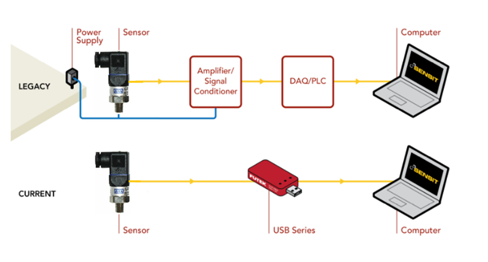
The assembly and setup of a pressure sensor platform have vastly improved with the introduction of USB digital signal conditioners. The traditional assembly of a pressure transducer involved a sensor, signal conditioning electronics, a power supply, a data acquisition system and data logger and analysis software, on occasion a filter, and then a PC to capture and house the data.
Though traditional platforms are suitable for most test and measurement applications, they carry a laundry list of “side effects” with them. Cost, space, noise, accuracy, convenience, and temperature co-efficiency all become variables within that traditional setup. What the industry needed was a fast data exchange solution that wouldn’t be phased by such “side effects.” And there lied the answer, a single unit solution — the USB digital signal conditioner module.
What is a Pressure Sensor Amplifier?
Structurally, a strain gauge pressure transducer sensor is made of a metal body (also called flexure) to which the metal foil strain gauges are bonded. These pressure measuring sensors body is usually made of aluminum or stainless steel, which gives the sensor two important characteristics: (1) it provides the sturdiness to withstand high pressures and (2) it has the elasticity to minimally deform and return to its original shape when the pressure is removed.
A pressure sensor converts pressure into an electrical signal. FUTEK industrial pressure sensors utilize the piezoresistive effect, which is comprised of metal foil strain gauges mounted onto a diaphragm. As pressure changes, the diaphragm changes shape, causing the resistance in the strain gauges to change, allowing the pressure changes to be measured electrically. Our pressure sensors naturally produce an electrical signal in millivolts that varies proportionally with the pressure and the sensor excitation voltage (mV/V – millivolt per volt). FUTEK offers pressure sensors with internal analog amplifiers. The pressure sensors with built-in amplifiers generate signals either in varying voltage, i.e. ±10V, or varying current (i.e. pressure transducer 4-20ma output).
The strain gauges are arranged in what is called a Wheatstone Bridge amplifier Circuit (see below animated diagram). This means that four strain gages are interconnected as a loop circuit and the measuring grid that is measuring pressure is aligned accordingly.
The strain gauge bridge amplifiers provide regulated excitation voltage and convert the mv/V output signal into another form of signal that is more useful to the user. The signal generated by the strain gage bridge is a low strength signal and may not work with other components of the system, such as PLC, data acquisition modules (DAQ) or computers. Thus, a signal conditioner is needed to provide excitation voltage, noise filtering or attenuation, signal amplification, and output signal conversion.
What are the functions of a Pressure Sensor Signal Conditioner?
The function of a pressure sensor signal conditioning is to capture the signal from the sensor and convert it into a higher level of an electrical signal. These electronic devices are also known as pressure sensor signal converters, given it converts and modulates electrical signals. In order to do so, the mV/V low amplitude output of the sensor goes thru several different signal conditioning steps:
Excitation Voltage
Some sensors require an excitation voltage to feed the Wheatstone bridge and generate their output signal as a ratio of the input excitation voltage. Thus, you need to establish if your DAQ or PLC can support the sensor’s input voltage or excitation voltage requirements. Simply put, an unstable excitation voltage input leads to an unstable sensor output. In case you need an amplifier module for PLC or DAQ and they do not provide a stable input excitation voltage, the amplifier will be the excitation voltage source to ensure the sensor provides a reliable and consistent output signal.
Filtering
Analog sensor signals are susceptible to electrical noise and/or residual ripple voltage, which can distort or skew measurements. Noise needs to be filtered out before you can capture an accurate signal. DAQs and PLCs designed to interface directly with full-bridge sensors will include pass band and other forms of signal conditioning and filtration. In a low noise signal conditioner, electronic filters eliminate some effects on accuracy by removing electrical noise and ripple effect above and below the analog sensors signal range, resulting in a low signal-to-noise ratio.
Amplification
Sensors can output a signal in the nanovolt through millivolt range. When your DAQ or PLC is limited to measuring volts, you will need an amplifier to convert millivolts to a larger signal. Some PLCs and DAQs come with built-in amplification: others will require an external amplifier. What if your existing DAQ or PLC does not provide built-in amplification, signal conditioning, and a stable power source for sensor excitation? In that case vou will need an amplifier to fill in the shortfalls in your instrumentation.
Analog to Digital Conversion (ADC):
Some applications require digital output, which will require a signal conditioner module with an analog to digital converter (ADC). When selecting the digital amplifier for those applications, two critical parameters must be taken into consideration: noise-free resolution and sampling rate. FUTEK has a broad range of USB output modules that provides signal processing with internal high resolution capable of offering up to 21 ENOB and up to 19 bits noise-free resolution. Our entire USB pressure transducer amplifier module line has a ± 0.005% of FSR for both accuracy and non-linearity.
Some applications require an aggressive sampling rate, where a thousand samples per second maximum just won’t cut it. FUTEK’s USBs offer excellent sampling rates, ranging between 5 and 15k samples per second. Please note that resolution will differ as your sampling rate increases.
What is the USB520 USB Digital Pressure Signal Conditioner?
The USB520 Universal Signal Conditioner Module supports a wide range of sensor inputs such as ± 10 VDC, 0-20 mA, ±400 mV/V and TTL encoder pulses type inputs, USB520 USB Digital Signal Conditioner can be paired with various sensor types and eliminates the need for external power supply to the sensor and display equipment. The module is supplied by PC power through the USB bus, providing excitation voltage selectable 5-24 VDC / 1W to the sensor and simultaneously 5 VDC for Encoder.

The sensor output is digitized up to 4,800 SPS and processed by a microprocessor using the integrated high resolution (24 bits) analog to digital converter (ADC). As it supports a wide range of sensor inputs such as ± 10 VDC, 0-20 mA, ±400 mV/V and TTL encoder type inputs, the USB520 USB Digital Signal Conditioner can be paired with various sensor types, such as:
- String Pot Position Sensors (draw wire sensor);
- Rotary Torque Sensors;
- DC LVDT Displacement Transducer - LVDT Signal Conditioning Module;
- TTL Output Encoders to measure RPM and Angle;
- Incremental Encoder Signal Converter.
- Pressure Sensors.
The USB integration works hand in hand with FUTEK’s SENSIT Test and Measurement software, which allows users to monitor the actual output of the sensor in real-time. FUTEK developed DLL Libraries to allow USB520 to also work with other software such as LabView® and Visual Studio.
USB520 Features
- USB 2.0 Communication Link
- USB Bus-Powered (5V)
- Input/Output Short Circuit Protection
- Streaming ASCII Output
- Offered with DLL/Mac Dynamic Library
- CE Approved Class A (required for Medical and Aerospace applications)
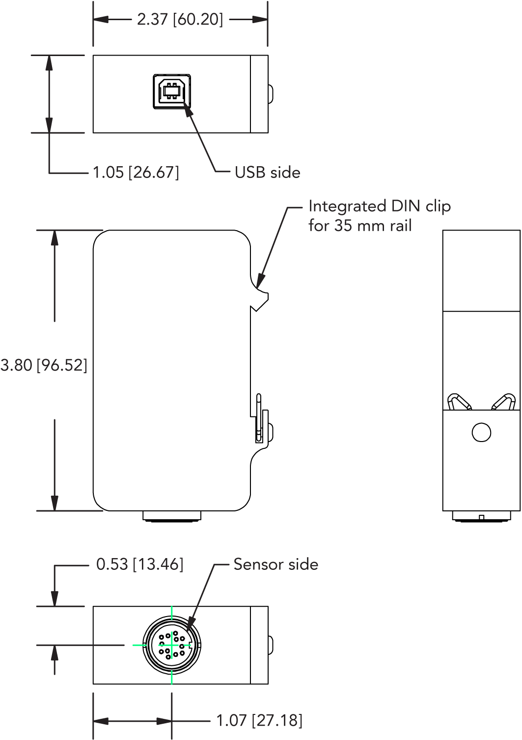
- Industrial metallic enclosure
- Integrated DIN rail mount
- Supports, VDC, mA, mV and TTL type input
What is the USB520 Signal Conditioner compatibility?
USB520 Universal Signal Conditioner Module supports a wide range of sensor inputs such as analog voltage (± 10 VDC), analog current (0-20 mA), Wheatstone Bridge (up to ±400 mV/V) and TTL encoder pulses type inputs. USB520 USB Digital Pressure Sensor Signal Conditioning can be paired with various sensor types and eliminates the need for an external power supply to the sensor and display equipment (load cell display).
USB520 pressure transducer amplifier is compatible with sensor models manufactured by most pressure transducer manufacturers:
- Omega
- Honeywell
- Wika
- Sensata
- SICK
- TE Connectivity
- Emerson
- Omron
- Yokogawa
- Amphenol
- Mouser
- And others.
Check USB520 spec sheet for signal input compatibility specs.
USB520 Technical Specifications
| SPECIFICATIONS | |
|---|---|
| GENERAL | |
| Sampling Rate | Up to 4800 SPS |
| Bandwidth (Hz) | Sampling Rate (SPS) / 4 |
| Internal Resolution | 24 bits |
| Non Linearity (max) | ±0.005% of FSR |
| Output | Digital Packetized Data |
| Integrated Digital Filter | 50 Hz/60 Hz Rejection (100 dB) |
| On Chip Memory | 1 Kilobyte |
| Stored Calibration | Up to 16 Points |
| Weight | 0.43 lb (195 g) |
| On Chip Sensor Profiles | Up to 4 |
| ASCII Output Update Rate | 10 SPS |
| IP Rating | IP50 |
| ENCODER INPUT | |
| Encoder Input | Quadrature Leading and Lagging Pulse (TTL) |
| Speed Measurement | Up to 150k Pulses Per Second¹ |
| Angle Measurement (α) | Up to 10k Pulses Per Rotation (PPR)¹ |
| Angle/Speed Measurement (Update Rate) | 100 ms |
| STRAIN GAUGE mV/V INPUT | |
| Bridge Excitation | 4.6 VDC |
| Standard Input Range | ±3.4 mV/V (factory default) |
| Optional Input Range | Up to ± 400 mV/V |
| Min. Bridge Resistance | 50 Ohm |
| Max. Bridge Resistance | 5000 Ohm |
| VOLTAGE INPUT | |
| Supply Voltage | Selectable 5,9,10,12,15,18,20,24 VDC/1W |
| Standard Input Range | ±10 VDC (Factory Default) |
| CURRENT INPUT | |
| Supply Voltage | Selectable 5,9,10,12,15,18,20,24 VDC/1W |
| Standard Input Range | 0-20 mA (Factory Default) |
| CONNECTORS | |
| Sensor Connector | Binder 09 0132 90 12 |
| Mating Connector | Binder 99 5129 00 12 |
| USB 2.0 Connector | Type B |
| ENVIRONMENT | |
| Operating Temperature | -13°F to 185°F [-25°C to 85°C] |
| Storage Temperature | -40°F to 257°F [-40°C to 125°C] |
| CONFORMITY | |
| RoHS | 2011/65/EU |
| CE | EN61326-1:2013; EN55011:2009 (Amended by A1:2010) |
¹ Speed = ∆ α × 60 / PPR
| SAMPLING RATE | ||
|---|---|---|
| SAMPLES PER SECOND (SPS) | mV/V RESOLUTION | mA AND VDC INPUT RESOLUTION |
| 5 | 18 | 20.5 |
| 50 | 16.5 | 19.5 |
| 100 | 16.3 | 19.2 |
| 300 | 15.8 | 18.2 |
| 1200 | 14.6 | 17 |
| 2400 | 13.6 | 16 |
| 4800 | 13.6 | 16 |
| DIMENSIONS inches [mm] |
|---|
What are the FUTEK USB Digital Signal Conditioners’ key differentials?
High Resolution

Resolution can be defined in three ways: internal, noise free, and effective number of bits. All USBs start at an internal resolution of 24 bits, and up to 21 ENOB. The noise free resolution of our devices can be up to 19 bits.
Impressive Accuracy & Non Linearity

FUTEK defines accuracy as a limit tolerance which defines the average deviation between the actual outputs versus theoretical output. And we define nonlinearity as the maximum deviation of the calibration curve from a straight line drawn between the no-load and rated load outputs. Knowing that both of these specifications are important, our entire USB line has a ± 0.005% of FSR for both accuracy and non-linearity.
Broad Sampling Rates

Some applications require an aggressive sampling rate, where a thousand samples per second maximum just won’t cut it. FUTEK’s USBs offer excellent sampling rates, ranging between 5 and 15k samples per second. Please note that resolution will differ as your sampling rate increases.
Low Noise Interference

Noise interference can be quite detrimental to your data collection, especially for delicate measurements in the milligram capacity ranges, so reducing the noise was our primary objective when designing the USBs.

FUTEK Certifications


FUTEK Social Media
FUTEK Address
19 Morgan, Irvine,
CA 92618 USA
CA 92618 USA


All other trademarks, service marks and logos used in this website are the property of their respective owners.
© 1998–2025 FUTEK Advanced Sensor Technology, Inc. All rights reserved.