Analysis of Long-Term Drift and Output Stability in Strain Gauge Load Cells
Analysis of Long-term Drift and Output Stability of FUTEK Strain Gauge Sensors
September 2025
Abstract
This paper presents a comprehensive summary of test results regarding zero drift and gain change observed during extended operational use. The conclusions are substantiated by rigorous in-house long-term endurance stress testing and customer-reported environmental stress test outcomes. Additionally, available technical literature demonstrates that resistive strain gages exhibit long-term stability, with overall drift of the resistive elements remaining below 30 ppm over a 19-year study period.
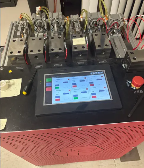
Figure 1. Long-term Endurance Test Stand
Experience with long-term drift of resistive strain gauge sensors
FUTEK has examined the various operating scenarios and environmental conditions that might cause long-term drift in zero-offset or gain shift over a sensor’s operational life. The company has conducted long-term endurance testing (Figure 1) over 24 years of accelerated stress testing of a representative sensor. This sensor is continually exposed to ambient environmental conditions and is currently subjected to a compression load of 113 lb, which is 13% above rated capacity. The system cycles at three samples per second and collects data every 1,000 cycles to monitor for failure. Routine calibration using precision deadweights is conducted in our laboratory to monitor its performance and record ongoing performance assessment. Throughout this 24-year period, the sensor has experienced less than a 0.28% change in output gain and less than 0.002 mV/V changes in zero balance (Figures 2 and 3). These results demonstrate that our sensors maintain exceptional stability over extended periods, consistently remaining within published specifications. Additionally, contemporary electronic systems mitigate potential zero-shift by compensating for any zero offset prior to commencing measurement operations.
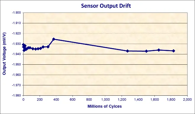
Figure 2. Sensor Output Drift Over Time
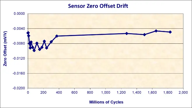
Figure 3. Sensor Zero Drift Over Time
Independent customer testing of 24 sensors, each subjected to alternating tension and compression to rated output across the full operational temperature range (-40° to +70°F) completed 1.25 million cycles (2.4 years of continuous testing at one load cycle per minute), showed a similar result. The average gain shifted by 0.24% over the entire test period, with no individual sensor drifting more than 1.3%.
These conclusions are further supported by published studies on the long-term stability of strain gauge load cells by Yorgiadis1 and strain gage stability over long periods of time by Tchebotarioff2. Yorgiadis concluded from his study of more than 15 companies that sensors that have been subjected to numerous environmental conditions for 10-20 years had an average stability shift of less than 0.5%. The Tchebotarioff study also found that the metal foil resistive material used by Vishay Micro Measurements Division to manufacture our strain gages experiences resistance changes of less than 30 ppm over a 19-year study period. This study was based on non-encapsulated strain gauges. FUTEK uses only factory-encapsulated strain gauges. Encapsulated strain gages provide a protection barrier against contamination and moisture reaching the resistive foil, thereby preserving the stability of strain gauge performance over time.
References
- Yorgiadis, Alexander, “Long term Stability of Strain gage Load Cells” Strainsert Company.
- G. P. Tchebotarioff, “Use of Electric Resistivity Strain Gages Over Long Periods of Time,” Proceedings of Society for Experimental Stress Analysis, v. III, pp. 47-52 (1946)