What is Center of Gravity (CG)?
The center of gravity (CG), also known as the center of mass, represents the average position of an object's weight distribution. Applying a force to or suspending an object from its center of gravity ensures it remains in equilibrium.
In the design of aircraft, spacecraft, and automobiles, calculating the center of gravity is critical as it affects dynamics, stability, and fuel efficiency. For example, aligning the rocket engine’s thrust vector with the vehicle’s center of gravity is essential for maintaining a stable trajectory.
How Are Load Cells Employed in Center of Gravity Scales?
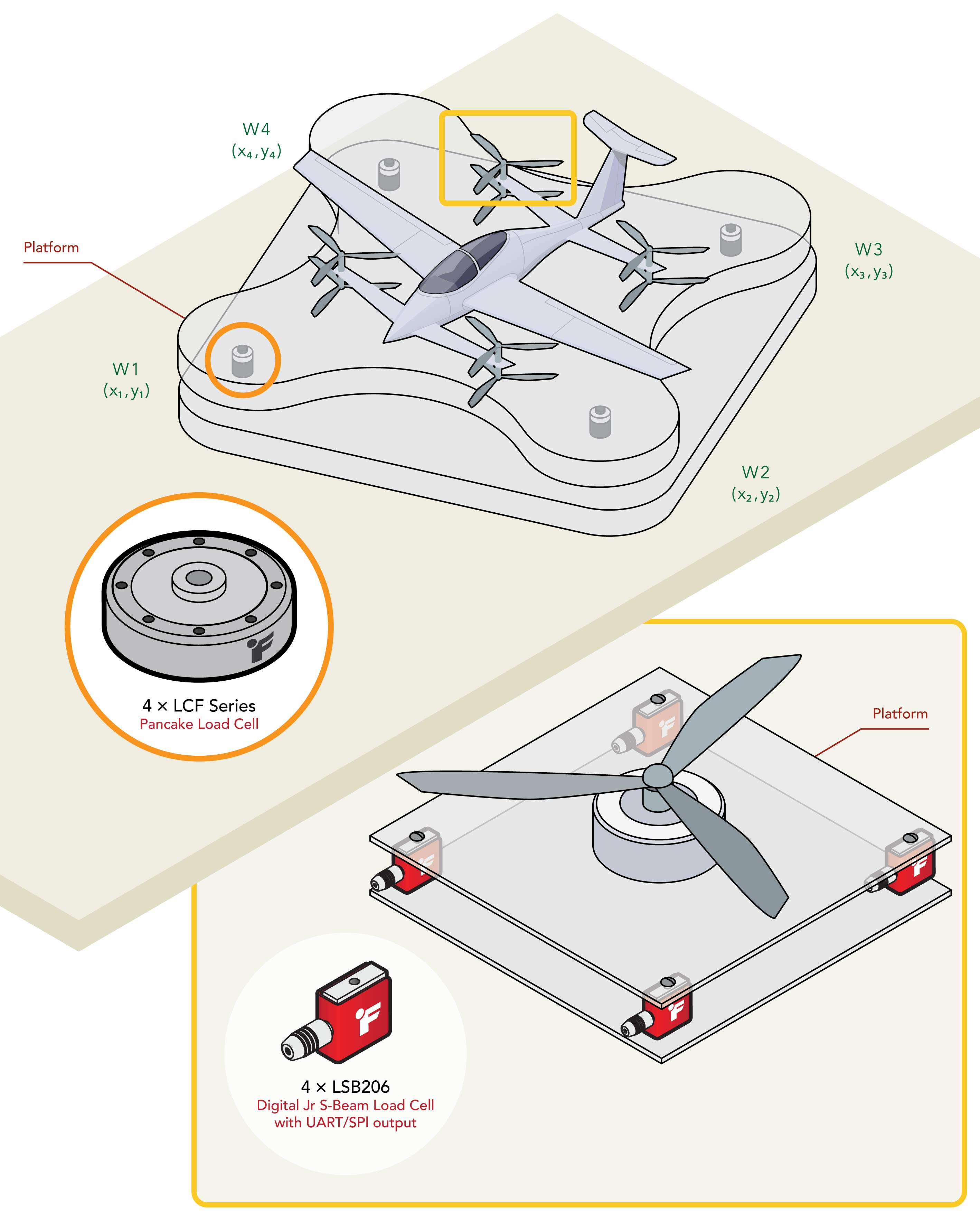
A center of gravity scale uses multiple load cells positioned at fixed, known locations on a weighing platform. When an object is placed on the platform, each load cell measures only the portion of the object's weight acting at its location. Since the load cells are at known positions relative to a fixed reference point (the origin), the difference in readings across sensors reflects how the object's weight is distributed across the platform. This distribution is what allows the center of gravity coordinates to be calculated.
The center of gravity can be calculated using the formula:
CoG = (ΣD* W) / ΣW
Where CoG represents the location of the center of gravity, D is the distance of each load cell from the origin and W is the load or weight measured at that position. This formula involves summing the product of distance and weight, and then dividing it by the sum of all the weights.
Applying this formula to a four-load-cell platform, the center of gravity coordinates are calculated independently for each axis as follows:
X-axis = (W1X1 + W2X2 + W3X3 + W4X4)/(W1+W2+W3+W4)
Y-axis = (W1Y1 + W2Y2 + W3Y3 + W4Y4)/(W1+W2+W3+W4)
Where W1–W4 are the loads measured at each sensor and X1–X4, Y1–Y4 are the known coordinates of each sensor relative to the origin.
To determine the center of gravity across all planes, the process can be repeated after rotating the object 90 degrees. This improves overall measurement accuracy
For large objects, such as VTOL (Vertical Take-Off and Landing) drones or aerospace capsules, FUTEK recommends the LCF Series Universal Pancake Load Cell. Its low profile, through-hole design, and wide capacity range of 25 to 100,000 lb make it ideal for a variety of center of gravity applications.
For small objects, such as propeller blades, FUTEK recommends LSB20x Miniature S-Beam Load Cell, which offer robust overload protection and capacities ranging from 10 g to 100 lb.
How it Works
Load Cell Installation: Mount load cells on the four corners of the center of gravity measurement platform, ensuring proper alignment and secure attachment. FUTEK’s A2LA-accredited calibration lab ensures all sensors ship with proper and traceable calibration.
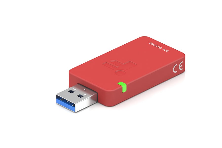
Signal Conditioner Installation: Connect the load cell outputs to an analog or digital signal conditioner before routing the signal to a DAQ or PLC.
Integration and Data Collection: Integrate the signal conditioners with a data acquisition system for real-time monitoring and analysis using FUTEK’s SENSIT™ Test and Measurement Software. The data collected can then be used to determine the center of gravity as per the formulas above.

Contact Us
Please Contact Us with questions.
What is Center of Gravity (CG)?
The center of gravity (CG), also known as the center of mass, represents the average position of an object's weight distribution. Applying a force to or suspending an object from its center of gravity ensures it remains in equilibrium.
In the design of aircraft, spacecraft, and automobiles, calculating the center of gravity is critical as it affects dynamics, stability, and fuel efficiency. For example, aligning the rocket engine’s thrust vector with the vehicle’s center of gravity is essential for maintaining a stable trajectory.
How Are Load Cells Employed in Center of Gravity Scales?
A center of gravity scale uses multiple load cells positioned at fixed, known locations on a weighing platform. When an object is placed on the platform, each load cell measures only the portion of the object's weight acting at its location. Since the load cells are at known positions relative to a fixed reference point (the origin), the difference in readings across sensors reflects how the object's weight is distributed across the platform. This distribution is what allows the center of gravity coordinates to be calculated.
The center of gravity can be calculated using the formula:
CoG = (ΣD* W) / ΣW
Where CoG represents the location of the center of gravity, D is the distance of each load cell from the origin and W is the load or weight measured at that position. This formula involves summing the product of distance and weight, and then dividing it by the sum of all the weights.
Applying this formula to a four-load-cell platform, the center of gravity coordinates are calculated independently for each axis as follows:
X-axis = (W1X1 + W2X2 + W3X3 + W4X4)/(W1+W2+W3+W4)
Y-axis = (W1Y1 + W2Y2 + W3Y3 + W4Y4)/(W1+W2+W3+W4)
Where W1–W4 are the loads measured at each sensor and X1–X4, Y1–Y4 are the known coordinates of each sensor relative to the origin.
To determine the center of gravity across all planes, the process can be repeated after rotating the object 90 degrees. This improves overall measurement accuracy
For large objects, such as VTOL (Vertical Take-Off and Landing) drones or aerospace capsules, FUTEK recommends the LCF Series Universal Pancake Load Cell. Its low profile, through-hole design, and wide capacity range of 25 to 100,000 lb make it ideal for a variety of center of gravity applications.
For small objects, such as propeller blades, FUTEK recommends LSB20x Miniature S-Beam Load Cell, which offer robust overload protection and capacities ranging from 10 g to 100 lb.