Why Rocket Thrust Testing is Critical to Engine Design and Efficiency
Static fire testing is an essential step in the development and validation of rocket engines. By securing an engine to a stationary thrust stand, engineers can accurately measure its thrust output and other performance parameters under controlled conditions. These tests provide data to identify design improvements, validate simulations, confirm safety margins, and ensure the engine meets mission requirements prior to flight.
Why use load cells in Thrust Testing
At the heart of a rocket thrust stand is the load cell, mounted in-line to measure axial thrust throughout a static fire test. The resulting thrust curve (force vs. time) reveals how the engine ignites, ramps up, sustains thrust, and shuts down. From this curve, engineers derive key performance metrics such as total impulse and specific impulse (Isp), which are critical for assessing engine efficiency and overall performance.
Rocket firings also produce rapid transients like ignition kicks that can cause sharp spikes in thrust. Capturing and analyzing these short duration events requires precise, high-bandwidth sensors. Load cells provide the accuracy, speed, and reliability needed to record such events.
FUTEK's LCF series are widely used in propulsion test stands due to their rugged construction and high accuracy. Custom versions with internal amplification simplify integration by allowing direct connection to DAQs or PLCs. For evaluating thrust vector control (TVC), FUTEK’s MTA500 multi-axis sensors provide high precision and bandwidth, and the capability to measure large forces and torques simultaneously. This enables real-time correlation of thrust direction and torque response, enabling accurate assessment of TVC systems.
Additional useful parameters can be measured by installing MTA400 and MTA600 triaxial sensors at the base of the thrust stand. These units detect off-axis forces, identify misalignment or structural deflection and even estimate propellant mass flow by tracking system weight change over time. Together, these sensors provide a comprehensive overview of engine behavior.
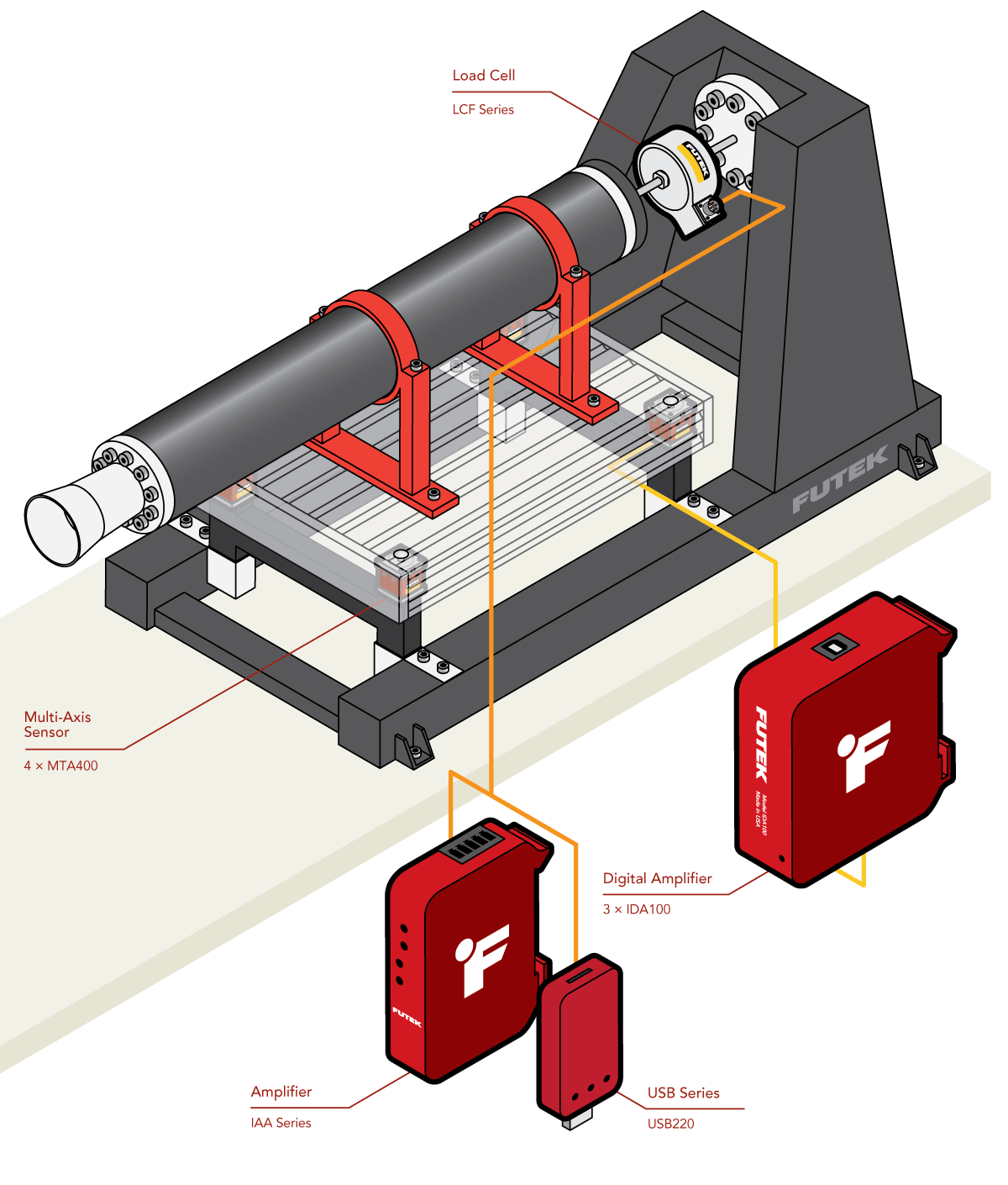
Rocket Engine Thrust Stand inspired by Swiss Propulsion Laboratory SPL's design.
Disclaimer: Illustrations are conceptual and do not represent complete systems. FUTEK provides sensors and instrumentation only; test fixtures and supporting structures must be sourced separately.
How it Works
A typical thrust measurement setup includes a thrust stand, high-frequency response load cell, signal conditioning electronics, and data acquisition software.
Thrust Stand Setup: The LCF load cell assembly is secured to the thrust stand securing the engine. The test stand mount prevents side loading, ensuring the load cell receives only axial loads.
Load Cell Installation: The rocket engine is threaded into the LCF series universal load cell.
Thrust Stand Setup: The LCF load cell assembly is secured to the thrust stand securing the engine . The test stand mount prevents side loading, ensuring the load cell receives only axial loads.
MTA400/MTA600 multi-axis load cells are installed at the base supports.
Thrust is measured by the LCF load cell.
Mass flow and ignition “kick” are captured by the MTA400/MTA600 sensors.
Signal Conditioner Installation: The output of load cells is routed to FUTEK's IAA series analog amplifiers or alternatively to USB225 Pro and Pro Elite for a streamlined digital connection from sensor to PC. Designed for high-speed data capture, the USB225 series provides the precision and reliability needed for rocket thrust testing.
Data Collection and Analysis: Thrust data collected via USB225 series or other DAQs can be displayed, logged, and analyzed using FUTEK’s proprietary SENSIT™ software to extract performance metrics, accelerating design decisions and reducing test iteration cycles.
Products in Use
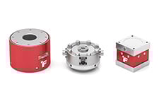
FUTEK’s Universal Load Cell (LCF Series) mated with instrumentation (IAA Series or USB220) and 4 of FUTEK’s MTA400/MTA600 Multi-Axis load cells each paired with 3 IDA100 digital amplifiers.
Contact Us
Please Contact Us with questions.
Why Rocket Thrust Testing is Critical to Engine Design and Efficiency
Static fire testing is an essential step in the development and validation of rocket engines. By securing an engine to a stationary thrust stand, engineers can accurately measure its thrust output and other performance parameters under controlled conditions. These tests provide data to identify design improvements, validate simulations, confirm safety margins, and ensure the engine meets mission requirements prior to flight.
Why use load cells in Thrust Testing
At the heart of a rocket thrust stand is the load cell, mounted in-line to measure axial thrust throughout a static fire test. The resulting thrust curve (force vs. time) reveals how the engine ignites, ramps up, sustains thrust, and shuts down. From this curve, engineers derive key performance metrics such as total impulse and specific impulse (Isp), which are critical for assessing engine efficiency and overall performance.
Rocket firings also produce rapid transients like ignition kicks that can cause sharp spikes in thrust. Capturing and analyzing these short duration events requires precise, high-bandwidth sensors. Load cells provide the accuracy, speed, and reliability needed to record such events.
FUTEK's LCF series are widely used in propulsion test stands due to their rugged construction and high accuracy. Custom versions with internal amplification simplify integration by allowing direct connection to DAQs or PLCs. For evaluating thrust vector control (TVC), FUTEK’s MTA500 multi-axis sensors provide high precision and bandwidth, and the capability to measure large forces and torques simultaneously. This enables real-time correlation of thrust direction and torque response, enabling accurate assessment of TVC systems.
Additional useful parameters can be measured by installing MTA400 and MTA600 triaxial sensors at the base of the thrust stand. These units detect off-axis forces, identify misalignment or structural deflection and even estimate propellant mass flow by tracking system weight change over time. Together, these sensors provide a comprehensive overview of engine behavior.
Rocket Engine Thrust Stand inspired by Swiss Propulsion Laboratory SPL's design.
Disclaimer: Illustrations are conceptual and do not represent complete systems. FUTEK provides sensors and instrumentation only; test fixtures and supporting structures must be sourced separately.