Stated as a limit tolerance which defines the average deviation between the actual output versus theoretical output. In practical transducer applications, the potential errors of nonlinearity, hysteresis, nonrepeatability and temperature effects do not normally occur simultaneously, nor are they necessarily additive. Therefore, accuracy is calculated based upon the RMS value of potential errors, assuming a temperature band of ± 10° F, full rated load applied, and proper set up and calibration. Potential errors of the readout, crosstalk, or creep effects are not included.
A load applied along a line concentric with the Primary Axis.
A record of the comparison of the transducer outputs versus standard test loads.
The range of temperature over which the transducer is compensated to maintain Rated Output and Zero Balance within specified limits.
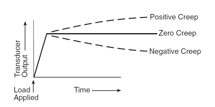
Creep is a positive or negative drift in sensor output caused by deformation of a sensor under constant load and environmental conditions over a period of time. This is due to a combination of inherent material properties, temperatures, sensor design, and strain gauge selection. FUTEK sensors utilize advanced methods and components that offset creep and greatly minimize this influence. Typically, the rate of change decays over time so the output stabilizes within several minutes.
With one component loaded to capacity, and the other unloaded, the output of the unloaded component will not exceed the percentage specified of its full scale capacity.
The change in length along the Primary Axis of the load cell between no-load and Rated Load conditions.
A random change in Output under constant Load conditions.
The algebraic difference between the indicated and true value of the load being measured.
The voltage or current applied to the input terminals of the transducer.
The comparison of transducer outputs against standard test loads. Load cell, torque sensors, and pressure transducers ought to be calibrated frequently. FUTEK Engineering Team recommends yearly calibration for our sensors. In case of a sensor paired to a signal conditioner, both the sensor and amplifier must be calibrated as a whole system.
The maximum difference between the transducer output readings for the same applied load; one reading obtained by increasing the load from zero and the other by decreasing the load from Rated Output. Usually measured at half Rated Output and expressed in percent of Rated Output. Measurements should be taken as rapidly as possible to minimize Creep.
The weight, torque, or force applied to the transducer.
A device which produces an Output signal proportional to the applied weight or force.
The full voltage output of the load cell is expressed in terms of its supply voltage. For instance, a 2mV/V load cell would produce 2mV times the supplied voltage at full capacity.
The frequency of free oscillation under no-load conditions.
The maximum Deviation of the Calibration Curve from a straight line drawn between the no-load and Rated Load outputs, expressed as a percentage of the Rated Output and measured on increasing load only.
The maximum difference between transducer output readings for repeated loadings under identical loading and environment conditions.
The extremes of temperature within which the transducer will operate without permanent adverse change to any of its performance characteristics.
The axis along which the transducer is designed to be loaded; normally its geometric centerline.
The maximum Axial Load that the transducer is designed to measure within its specifications.
The signal (voltage) produced by the transducer. Where the output is directly proportional to excitation, the signal is expressed in terms of millivolts / volt (mV/V) of excitation.
The maximum, temporary or accidental load in percent of Rated Capacity which can be applied without producing a permanent shift in performance characteristics beyond those specified.
Electrical simulation of transducer output by insertion of known shunt resistors between appropriate points within the circuitry.
The change in Output due to a change in transducer temperature. Expressed as a percentage of load per degree Fahrenheit (Celsius) change temperature.
The change in Zero Balance due to a change in transducer temperature. Expressed as the change in Zero Balance in percent of Rated Output per degrees Fahrenheit (Celsius) (change in temperature).
The output signal of the transducer with rated Excitation and with no-load applied, usually expressed in percent of Rated Output.
The difference in Zero Balance measured immediately before Rated Load application of specified duration and measured after removal of the load, and when the output has stabilized.
The degree to which the transducer maintains its Zero Balance with all environmental conditions and other variables remaining constant.