Extraneous Load Factors
Doc#: EL1017 Model #LCF250
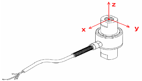
Equation: σmax ≥ (A)Fx + (B)Fy + (C)Fz + (D)Mx + (E)My + (F)Mz
Material: 17-4 P.H. Stainless Steel
| MODEL # | CAPACITY (lb) | A | B | C | D | E | F |
|---|---|---|---|---|---|---|---|
| LCF250 | 2,000 | 840.99 | 840.99 | 30.49 | 717.81 | 717.81 | 606.25 |
| 3,000 | 511.70 | 511.70 | 20.46 | 446.51 | 446.51 | 402.40 |
Table: σmax
| Material | Static Load (=60% Y.S.) | Fatigue (Non Reversing Loads) | Fatigue (Full Reversing Loads) |
|---|---|---|---|
| 17-4 PH S.S. | 87,000 | 78,000 | 62,000* |
*Value is 75% of Fatigue Strength based on 10-20 x 106 cycles and allow for factors that influence Fatigue such as surface finish, stress concentrations, corrosion, temperature and other variables for the production of the transducer, for infinite Fatigue Life (100 x 106) use 75% of values shown.
Deflection & Natural Frequency
| MODEL # | CAPACITY (lb) | DEFLECTION (in.) | NATURAL FREQUENCY (Hz) | β |
|---|---|---|---|---|
| LCF250 | 2,000 | 0.0010 | 16,200 | 0.0718 |
| 3,000 | 0.0015 | 18,500 | 0.0718 |
*FN results are based on calculation of deflection & weight scene on sensor arm.
Natural Frequency & Frequency response equations:
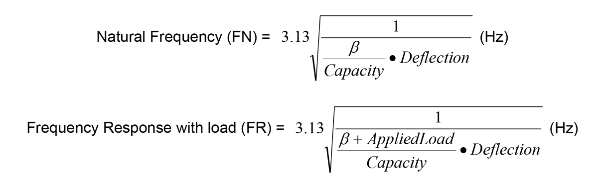
*Where β values are obtained by FUTEK Engineers