Load Cell Sizing | How to Select your Load cell? | FUTEK
Important Considerations in Selecting a Load Cell
Selecting a sensor is a difficult task since no 1 sensor fits all applications. There is no real industry standard on how you go about selecting your product. Other challenges you may encounter include finding compatible instrumentation or requiring a non-standard product that could increase delivery time. Even after you pick the right sensor, it will not give you satisfactory results if it is installed incorrectly. It is also important to find a sensor manufacturer that has the experience to support your needs before and after the sale.
Step 1
In order to keep these challenges to a minimum, here are some key things to consider during your selection process. Understanding your application and defining your requirements are a critical part of this procedure. After you’ve clearly defined your application, define what it is you want to measure. Do you want to measure load? This means that you want to convert input mechanical force into an electrical signal. Note that load cells are different than pressures sensors. Load cells can be used to measure surface pressure. However you would use a Pressure Sensor if you need to measure fluid or gas pressure. Load Cell Applications include pressure to viscosity/liquid separation, automation, medical bag weighing, and many more. Here are a few Load Cell Applications that may help guide you in your selection.
Step 2
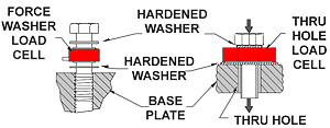
Then take a look at some of the key characteristics that would define your needs. Do you have static load or is it a dynamic type? Define the mounting type. How will you be mounting this load cell? Is it Female/Male thread, In-line, Side Mount, Flange Mount, Thru-hole, or Compression Washer? What is your load direction? (Tension, Compression, or both.)
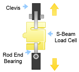
In-Line Diagrams
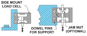
Side Mount Diagrams
Step 3
Determining your capacity requirements is just as important as the aforementioned characteristics. Define your minimum and maximum capacity requirements. Be sure to select the capacity over the maximum operating load and determine all extraneous load and moments prior to selecting the capacity. Note: extraneous load and moments increase combined stress which accelerates fatigue and will also affect the performance and accuracy if the correct load cell is not selected. Most in-line sensors such as the S-Beam are not designed with extraneous load and moment capability. For endurance or fatigue applications try to operate at 50% or lower of the rated capacity or use a Fatigue Rated Sensor already designed by the manufacturer.
Step 4
Next define your size requirements (width, weight, height, length, etc) and specification requirements (output, nonlinearity, hysteresis, creep, bridge resistance, resolution, frequency response etc.) Other characteristics to consider include submersible, cryogenic, high temperature, multiple or redundant bridges, and TEDS IEEE1451.4.
If you need an instrument for your application, select the instrument at the same time you select the load cell. This will help ensure compatibility of the entire measurement system. Don’t forget to purchase system calibration with your order. This integrates your sensor and instrument as one system.
If you need an instrument for your application, select the instrument at the same time you select the load cell. This will help ensure compatibility of the entire measurement system. Don’t forget to purchase system calibration with your order. This integrates your sensor and instrument as one system.
Summary
Remember, these tips are guidelines to help point you in the right direction when selecting your sensor. It is very important to find a sensor manufacturer that has proven experience and resources to support your needs. Find out if the company has worked with similar applications in the past. If it is a completely new application in which there is no precedence, select a company that has a reputation for taking on these new challenges and would be able to work with you every step of the way from design through to manufacturing and implementation. If you require a nonstandard product, note that your expected delivery time will increase by at least one month.