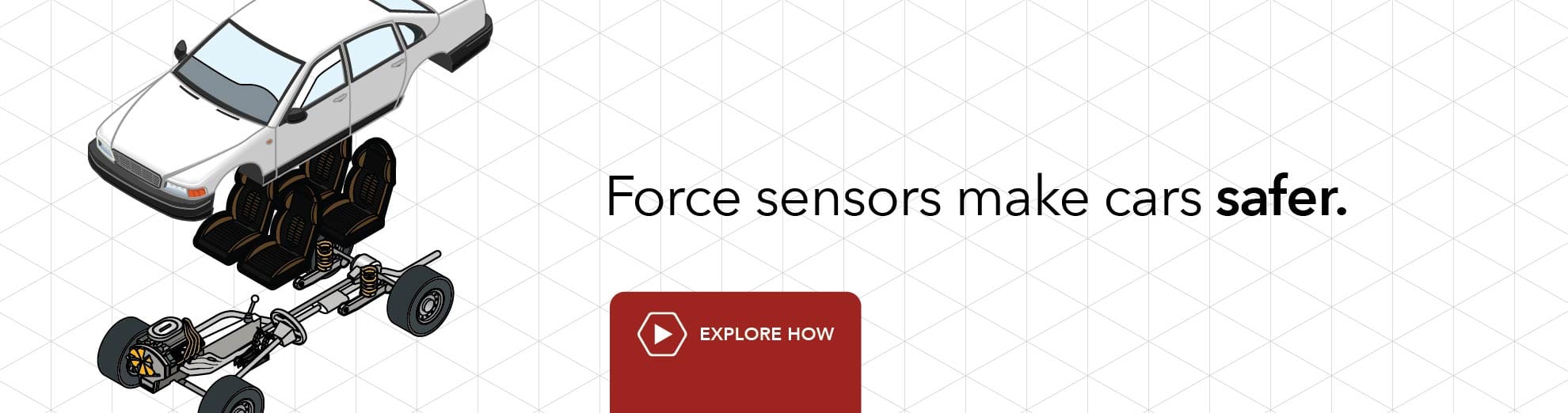
Load Cell Accuracy: Definition, Specifications, and Measurement Factors
What is Load Cell Accuracy?
An important concept regarding force transducers is load cell sensitivity and accuracy. Force Sensor accuracy can be defined as the smallest amount of force that can be applied to the sensor body required to cause a linear and repeatable variation in the voltage output. The higher the load cell accuracy, the better, as it can consistently capture very sensible force variations. In applications like high precision factory automation, surgical robotics, and aerospace, load cell accuracy is paramount. Some of our load cells offer Nonlinearity, Hysteresis and Nonrepeatibility of ± 0.02% of Rated Output (i.e. LSM305).
Why is it important to calibrate load cell and torque sensors?
Load Cell Calibration is an adjustment or set of corrections that are performed on a load cell, or instrument (amplifier), to make sure that the sensor operates as accurately, or error-free, as possible.
Every sensor is prone to measurement errors. These structural uncertainties are the simply algebraic difference between the value that is indicated by the sensor output versus the actual value of the measured variable, or known reference loads. Measurement errors can be caused by many factors:
An offset means that the sensor output at zero load (true zero) is higher or lower than the ideal output. Additionally, zero stability relates to the degree to which the transducer maintains its zero balance with all environmental conditions and other variables remaining constant.
Few force sensors have a completely linear characteristic curve, meaning that the output sensitivity (slope) changes at a different rate throughout the measurement range. Some are linear enough over the desired range and does not deviate from the straight line (theoretical), but some sensors require more complex calculations to linearize the output. So, load cell non-linearity is the maximum deviation of the actual calibration curve from an ideal straight line drawn between the no-load and rated load outputs, expressed as a percentage of the rated output. The LSM300 High Precision Load Cell offers a lightweight design with a side mounting feature ideal for OEM applications.
The maximum difference between transducer output readings for the same applied load; one reading is obtained by increasing the load from zero and the other by decreasing the load from the rated output. It usually measured at half rated output and expressed as a percentage of the rated output. Measurements should be taken as rapidly as possible to minimize creep.
The maximum difference between transducer output readings for repeated loadings under identical loading and environmental conditions. It translates into the load cell's ability to maintain consistent output when identical loads are repeatedly applied.
The change in output and zero balance, respectively, due to a change in transducer temperature.
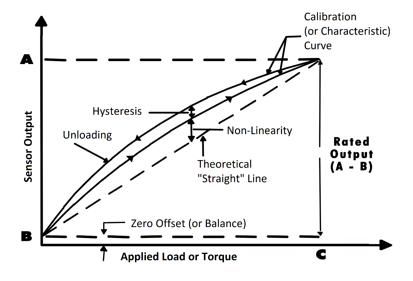
Each force sensor has a "characteristic curve" or a "calibration curve", which defines the sensor's response to an input. During a regular calibration using the load cell calibration machine, we check the sensor's zero offset and linearity by comparing the sensor output under reference weights and adjusting the sensor response to an ideal linear output. The load cell calibration equipment also check hysteresis, repeatability and temperature shift when customers request it for some critical force measurement applications.
For more information about calibration (calibrate measurement transducer), please refer to our Force Sensor Calibration FAQ Page.
If you have further questions about calibration terms and definitions, please refer to our Force Transducer Calibration Terms Glossary.
Find out info on basic measurement concepts such as sensor resolution, sensor accuracy, and the differences between resolution versus accuracy, and precision vs resolution.

How often should a load cell be recalibrated?
As strain gauge load cells are exposed to continuous usage, aging, output drift, overload and improper handling, FUTEK highly recommends a yearly recalibration interval. Frequent recalibration helps confirm whether the sensor maintained its accuracy over time and provides a load cell calibration certificate to show that the sensor still meets specifications.
However, when the sensor is used in critical applications and harsh environments, load cells may require even more frequent calibrations. Please consult with our Technical Support team, who will help you evaluate the most economical calibration service interval for your force sensor.

Due for recalibration?
Because our products are used in critical applications that require exact specifications, we have created a recalibration program that continuously supports our customer's needs for verification and alignment. We also offer recalibration services to customers who have purchased test and measurement products from the following manufacturers:
- Honeywell/Sensotec/Lebow
- Interfaceforce
- Omega
- Transducer Techniques
- HBM
- Himmelstein
- Strainsert
- See a complete list of Non-FUTEK sensors serviced by our Calibration Lab
What is system calibration (sensor plus amplifier/instrument)?
A system calibration provides the signature of the performance of the sensor and instrument together ("calibration curve") and ensures that the combination of the results meet specifications. A force measurement system usually encompasses the weight sensor, instrument or signal conditioner (i.e.: load cell indicator or signal conditioner), cabling, and connectors. Full system calibration ensures that the whole system is performing accurately as expected.
Check out below a video on the "Benefits of System Calibration":
Choosing complete system calibration allows you to start using your load measurement solution out of the box. A system calibration creates a plug & play solution where all connectors, cables, and instrument settings are taken care of.
As an A2LA certified calibration lab, FUTEK offers full system calibration for sensors with digital displays, digital load cell amplifiers, and/or USB solutions, and use calibration procedures in compliance with ISO 17025 standards. FUTEK's certification includes accreditation to ANSI/NCSL Z540-1.
What are the different types of load transducer calibration procedures?
One-point calibration is the simplest type of calibration and it is recommended for applications that only require accurate measurement at a single load or torque. If the force sensor is known to be linear, repeatable, and has the correct slope over the desired measurement range, a one-point calibration can be applied to adjust the zero offset error (zero balance).
A one-point force transducer calibration also helps to verify "output drift" in order to correct any deterioration in sensor performance over time.
A two-point calibration is a little more intricate and more precise than a one-point calibration. In a two-point calibration, the sensor offset is adjusted at two different output values, resulting in a reasonably accurate straight line across the entire force measurement scale. It is typically recommended that the two points used are zero and the full scale (rated output).
Load cell and torque sensors are known to be reasonably linear over the measurement range (or rated output), thus a two-point calibration is often recommended, given that a two-point calibration essentially re-scales the output by correcting both the slope (load cell sensitivity) and offset (zero balance) errors.
With the new zero offset and slope (load cell sensitivity), one can determine the linear equation that characterizes the sensor output (Vout=Sensitivity*Load + Zero_Offset).
Some critical applications require a high degree of accuracy over a very specific measurement range of the force sensor. In these cases, a five-point load cell calibration services and curve fitting are required to characterize the calibration curve and achieve measurement output over the specified output range.
Normally, a five-point calibration is performed by taking the output at 0%, 20%, 40% 60%, 80%, 100% of the required measurement range:
- 0%: Zero offset adjustment (or zero balance);
- 20%, 40%, 60%, 80%: Linearity adjustments;
- 100%: Span or slope adjustment (sensitivity).
In the five-point force sensor calibration process, the output readings are taken in the upscale and downscale values to determine the repeatability and hysteresis of the force measurement system (sensor + signal conditioner).
As most of the load cell or torque transducers are paired with a readout display or signal conditioner to form a turnkey force or torque measurement system, the instrumentation should always be hooked up with the sensor and be calibrated together as a system (check this torque calibration tool application). That said, consider for example a 50 lbs LSB205 Miniature S-beam Load cell (or any other micro load cell) paired with an IAA200 4-20mA Current output amplifier and a 10ft long cable. When requested by the customer, the five-point output readings would be taken when the sensor is subjected to loads of 0 (no load), 10 lbs, 20 lbs, 30 lbs, 40 lbs and 50 lbs upward scale and downward scale.
| % of full scale | Applied Load (lbs.) | Amplifier Output (mA) |
|---|---|---|
| 0% - No Load | No Load | 4 mA |
| 20% | 10 lbs | 7.2 mA |
| 40% | 20 lbs | 10.4 mA |
| 60% | 30 lbs | 13.6 mA |
| 80% | 40 lbs | 16.8 mA |
| 100% - Full Scale | 50 lbs | 20 mA |
| 80% | 40 lbs | 16.8 mA |
| 60% | 30 lbs | 13.6 mA |
| 40% | 20 lbs | 10.4 mA |
| 20% | 10 lbs | 7.2 mA |
| 0% - No Load | No Load | 4 mA |
Depending on the application requirements, this procedure is repeated twice or multiple times. The difference in the outputs is utilized to calculate the non-repeatability (or repeatability) and linearity (accuracy).
We are frequently questioned on How to calibrate a torque wrench? This can be accomplished by utilizing FUTEK’s TDF Torque Sensor as a torque wrench calibration tool to verify the precision of a torque wrench.
How a Load Cell works (Force Sensor Working Principle)
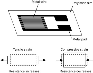
Firstly, we need to understand the underlying physics and material science behind the straing strain gauge load cell working principle, which is the strain gauge (sometimes referred to as Strain gage). Metal foil strain gage is a sensor whose electrical resistance varies with applied force. In other words, it converts (or transduces) force, pressure (i.e. pressure sensors), tension, compression, torque, weight, etc… into a change in electrical resistance, which can then be measured.
Strain gauges are electrical conductors tightly attached to a film in a zigzag shape. When this film is pulled, it – and the conductors – stretches and elongates. When it is pushed, it is contracted and gets shorter. This change in shape causes the resistance in the electrical conductors to also change. The strain applied in the load cell can be determined based on this principle, as strain gauge resistance increases with applied strain and diminishes with contraction.
Structurally, a force sensor (or transducer) is made of a metal body (also called flexure) to which foil strain gauges are bonded. The sensor body is usually made of aluminum or stainless steel, which gives the sensor two important characteristics: (1) provides the sturdiness to withstand high loads and (2) has the elasticity to minimally deform and return to its original shape when the force is removed.
When force (tension or compression) is applied, the metal body acts as a “spring” and is slightly deformed, and unless it is overloaded, it returns to its original shape. As the flexure deforms, the strain gage also changes its shape and consequently its electrical resistance, which creates a differential voltage variation through a Wheatstone Bridge circuit. Thus, the change in voltage is proportional to the physical force applied to the flexure, which can be calculated via the load cell circuit voltage output.
These strain gauges are arranged in what is called a Wheatstone Bridge Circuit (aka Load Cell Circuit). This means that four strain gages are interconnected as a loop circuit (load cell circuit) and the measuring grid of the force being measured is aligned accordingly.
The strain gauge bridge amplifiers (or load cell signal conditioners) provide regulated excitation voltage to the load cell circuit and convert the mv/V output signal into another form of signal that is more useful to the user. The signal generated by the strain gage bridge is low strength signal and may not work with other components of the system, such as PLC, data acquisition modules (DAQ), computers, or microprocessors. Thus, force sensor signal conditioner functions include excitation voltage, noise filtering or attenuation, signal amplification, and output signal conversion.
Furthermore, the change in the amplifier voltage output is calibrated to be linearly proportional to the Newtonian force applied to the flexure, which can be calculated via the load cell circuit voltage equation.