Load Cell Signal Conditioner | How it Works | FUTEK
What is a load cell signal conditioner?
What is a load cell signal conditioner’s job?
When measuring force in real world applications, electronics bridge the gap between mechanical systems and digital devices. Strain gauge-based sensors measure and convert physical quantities such as force into measurable electrical signals. In order for this data to be read, the sensor needs to be interfaced with data acquisition systems (DAQ) or PLCs without losing meaningful information in the process. Signal conditioners (strain gauge-based signal conditioners/amplifiers) help with this conversion. They also boost the signal, improving its resolution while filtering noise from the external environment.
What challenges do strain gauge amplifiers/signal conditioners solve?
Besides boosting and filtering the strain gauge output as described in the above steps, signal conditioners can also help in mitigating other factors that affect the measured signal. Below are some common challenges that can be mitigated with electronics:
Excitation: The wheatstone bridge used in conjunction with strain gauge-based sensors requires an external excitation voltage to generate an output. To achieve a clean output, a clean input voltage (excitation) must be provided. Hence, it’s critical to use excitation circuitry capable of generating a clean, low drift excitation signal.
Sensitivity Error: The slope of the characteristic output curve of a sensor defines the sensor’s sensitivity. The amount of deviation from the ideal curve defines the sensitivity error, which can result in anon-symmetric response and also impact the dynamic range (the total range (minimum to maximum) that can be measured during normal operation). To minimize this error, the deviation must be addressed by the electronics connected to the sensor.
Precision: The precision of a sensor is defined as its ability to consistently produce the same output under identical conditions. an ideal sensor should output the same value given the same input stimuli. In practice, a sensor’s output is impacted by external factors, such as materials used for fabrication and the tolerances involved in manufacturing processes. At FUTEK, we have invested significant time into investigating and analyzing our manufacturing processes to identify potential errors. We have developed solutions for every step and integrated those learnings into our electronics design process as well.
Sensor Resolution: The smallest change in force that a sensor can reliably measure. It is typically given in newtons (N) or as a percentage of full scale Downstream conditioning electronics must be capable of resolving the output of the sensor to provide a precise measurement.
Offset Error: This error cannot be completely eliminated ,and electronics are needed to limit its effects.
Linearity Error: The linearity of the sensor refers to how closely a sensor’s output matches a straight line curve across its measurement range. Linearity error is the deviation between the sensor’s output and this ideal straight-line curve. Amplifiers and signal conditioners also exhibit linearity errors. Therefore, it is important to design circuits with errors significantly lower than the sensor error. This ensures that the overall system non-linearity doesn’t far exceed the non-linearity of the sensor. In some extreme cases, electronics are designed to perform linearization. This approach adds complexity, requiring digital/firmware development and enhanced calibration to account for the unique non-linearity characteristic error of every sensor.
There are other sensor errors that electronics can help to mitigate, such as Hysteresis, Response Time, Bridge Resistance, Sensor Drift etc. To learn more about these terms, please see FUTEK’s glossary.
How do FUTEK load cell signal conditioners solve other common challenges?
FUTEK specializes in designing sensors for high-performance applications such as multi-axis surgical tools and robotic limbs. To meet the most stringent requirements, Our design team consistently pushes the boundaries of sensor design, optimizing for critical factors such as calibration, amplification, and filtering. We try to identify the most common failure scenarios and offer custom solutions to mitigate them. These offerings aren’t standard across the industry. They are a testament to our unwavering commitment to provide our customers with the necessary reliability and performance across our range of sensors.
Fault Detection: Our signal conditioners and amplifiers have the capability to detect excitation faults (open/short) which can be flagged via a digital pin or the transfer of a data packet. For example, both High Resolution & Speed USB Output Kit and Digitally Configurable Analog Voltage Amplifier have multiple fault detection features, such as indicating over-temperature and over current/voltage events.
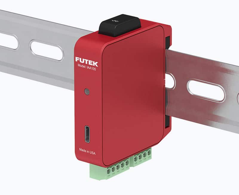
Onboard Temperature: We utilize onboard temperature measurement to ensure our products always operate under nominal conditions. As an example, our Digitally Configurable Analog Voltage Amplifier has an on-board temperature sensor that continuously monitors the temperature of the board. If the temperature falls outside of IAA105’s operating range (-20°C to 70°C), a red LED signals a fault. For embedded electronic solutions, the distance between the bridge and the electronics is minimal. Therefore, the measured temperature provides a reliable estimation of the bridge temperature. This proximity enables better temperature compensation of the bridge, improving the accuracy of the overall system .
Both USB225 Pro and Pro Elite feature an LED to indicate fault conditions, along with on-board temperature sensors. These compact, high-resolution signal conditioners also feature packet acknowledgment with error checking (CRC/checksum) to ensure reliable data communication, an essential requirement for medical device applications.
Low Power Consumption: For critical applications requiring ultra-low power consumption, we allow the customer to continuously monitor the overall power consumption, and either shut down or force the FUTEK sensor into a low power mode. Our electronics are also engineered for low power consumption. For example, the Digitally Configurable Analog Voltage Amplifier operates efficiently at just 1.2W, while the Ultra-Low Power Miniaturized Integrable Sampling System consumes only 60mW.
Protection: All exposed pins in FUTEK’s electronic designs feature protection against unexpected electrical events. Our design approach balances protection and performance to ensure the best possible outcome for the customer. Depending on the application, we provide certifications such as CE and MTBF.
PCB Design and Material Selection: In mixed system design, proper isolation between analog and digital circuitry is a key requisite for reliable performance. Because FUTEK designs its own electronics, including the PCBs (Printed Circuit Boards), we have the flexibility to optimize layout and component selections. PCB materials and electronic components are carefully chosen based on environmental demands, ensuring reliable performance in challenging conditions such as high humidity, vibration, and extreme temperatures.
Low Impedance: FUTEK signal conditioners have been designed to be compatible with most devices on the market. Their low output impedance offers flexibility when connecting to external devices such as DAQs or PLCs.
Noise Immunity: Our signal conditioners and amplifiers feature robust enclosures, such as inner metallic shielding and external chassis that enhance noise immunity. To learn more about how to reduce electrical noise in your system, see our guide.
Low Non-Linearity: Linearity is defined as the amount of deviation of the measured output curve of a sensor versus the ideal straight line curve. FUTEK designs electronics with exceptionally low non-linearity (as low as > 0.002%), ensuring reliable, accurate performance. FUTEK’s innovative single-unit USB solutions offer exceptional resolution (up to 20 bits) and high sampling rates (max SPS 38,400), maximizing sensor performance
How do sensors and strain gauge amplifiers/signal conditioners communicate?
Sensors and signal conditioners communicate with each other using signals transmitted via a device-to-device standardized communication protocol. Below is a breakdown of the different types of output:
What is analog voltage?
An analog voltage signal is an electrical signal that varies smoothly over time and is measured in volts. Analog voltage signals are used to transmit continuous data especially in low-power applications.
What is analog current?
An analog current signal refers to an electrical signal that varies smoothly over time and is measured in amperes. Analog current signals are used to transmit continuous data especially in high-power applications.
USB
USB (Universal Serial Bus) digitizes a wide range of sensor inputs such as ± 10 VDC, 0-30 mA, ±400 mV/V using an integrated analog to digital converter (ADC). USB output is particularly well suited for test and measurement applications that require dynamic force capturing and processing. FUTEK’s Pro Elite High Resolution and Speed USB Output Kit is ideal for measurement applications requiring dynamic force capture as it offers high-speed sampling (up to 38,400 SPS) and advanced filtering capabilities, ensuring accurate reproduction of input forces and enabling detailed analysis for validation and verification.
What is UART?
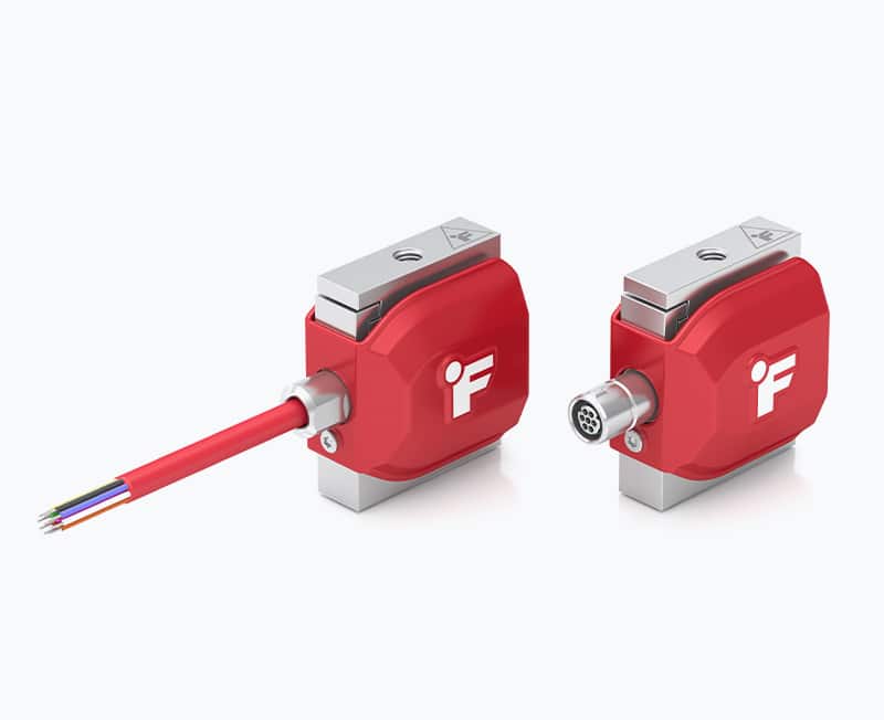
UART (Universal Asynchronous Receiver Transmitter) is a widely-used serial communication protocol in embedded systems valued for its simplicity and ease of implementation. It transmits data sequentially, one bit at a time over a communication channel without the need for a synchronized shared clock. Common serial UART communication protocols include RS-232, RS-485, USB (Universal Serial Bus), and SATA (Serial ATA). FUTEK’s Digital Jr S-Beam Load Cell 3.0. is a smart sensor with embedded electronics and flexible digital output options. It is available in two versions: one offering UART only communication and another supporting both SPI (Serial Peripheral Interface) and UART connectivity.
What is analog current?
An analog current signal refers to an electrical signal that varies smoothly over time and is measured in amperes. Analog current signals are used to transmit continuous data especially in high-power applications.
What is analog current?
An analog current signal refers to an electrical signal that varies smoothly over time and is measured in amperes. Analog current signals are used to transmit continuous data especially in high-power applications.
What are the different types of strain gauge amplifiers/signal conditioners?
Meet FUTEK’s flagship amplifiers/signal conditioners
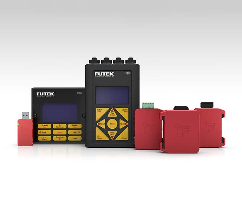
The choice of electronics depends on the setup and performance requirements of your application. FUTEK offers a wide range of amplifiers and signal conditioners, ranging from analog to digital solutions to panel displays and micro-mini embedded systems. Each unit is designed and manufactured to deliver next-level performance, well beyond conventional industry standards. Some of our most trusted models are featured below:
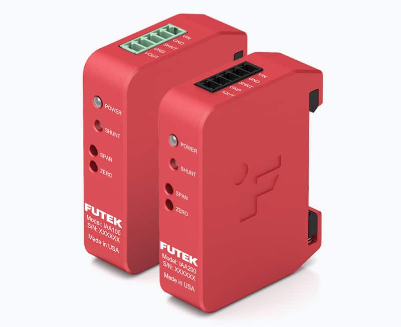
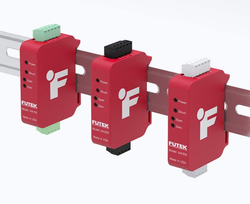
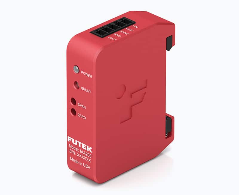
IAA100/IAA200 Analog Current and Voltage Amplifiers
The IAA100/200 models combine unsurpassed accuracy with ease of integration. Built with active protection circuitry, hot-swap capability, and a robust stainless steel chassis, IAA100/200 deliver exceptional reliability and precision under the harshest of conditions. These units offer in-line amplification of full bridge strain gauge type sensors with mV/V output and can be used in force measurement systems that require voltage or current output. The IAA100/200 provides bridge excitation voltages of either 5 or 10 VDC and amplifies sensor output from 0.5 mV/V to 10.0 mv/V. It offers three selectable bandwidth options (1 kHz, 25 kHz, and 50 kHz), and they feature an integrated DIN clip design ideal for industrial environments.
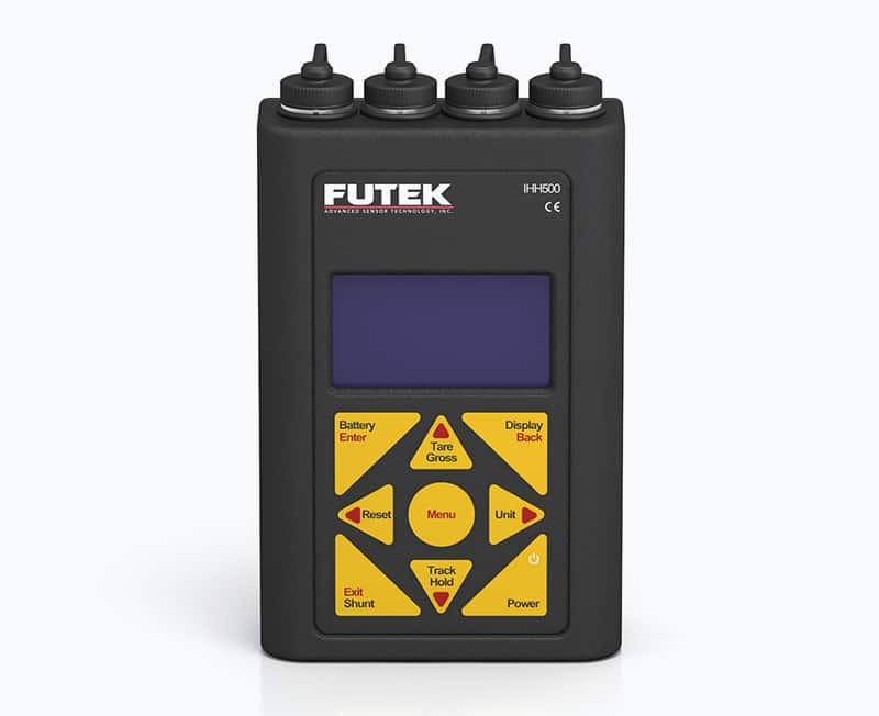
IHH Digital Hand Held Display
The IHH500 is a battery-operated handheld display that connects to a computer via USB. It’s suitable for strain-gauge-based load cells, torque sensors, and pressure sensors used in engineering applications. This digital weight indicator features an integrated low noise/high-speed/high-resolution ADC, accommodating various sensor inputs. Available in Pro and Elite versions, the IHH500 offers similar capabilities across models with the key distinction that the Elite version also reads and records encoder data like angle and speed. Both versions also include FUTEK’s SENSIT® software for live graphing and logging of data.
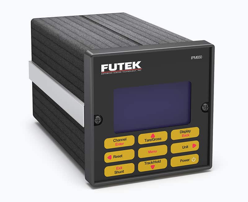
The IPM650 Panel Mount Display
FUTEK’s IPM650 panel mount display, also known as a load cell readout, is an all-in-one standalone solution with a very high sampling rate of 4,800 SPS and and a noise free resolution of 18.7 bits for mV/V inputs. This versatile multi-function display provides seamless USB (2.0) connectivity and supports a wide range of sensor inputs, including ±500 mV/V Strain Gauge, ±12 VDC, and 0-30 mA load cells, torque, and pressure sensors. Its panel mount design ensures secure integration with control systems, maximizing sensor performance due to lower noise and improved precision.
IAA105 Digitally Configurable Analog Voltage Amplifier
IAA105 is a groundbreaking fully digitally configurable analog amplifier offering unsurpassed flexibility and ease of use. Designed for maximum precision, the IAA105 delivers ultra low noise performance of 2.8 mVp-p, and offers extremely fine resolution with system calibration adjustable to as low as 300 µV. It’s configurable via Bluetooth® or USB. Built with active protection circuitry, hot-swap capability, and a robust stainless steel enclosure, the IAA105 delivers exceptional reliability even in the most demanding environments.
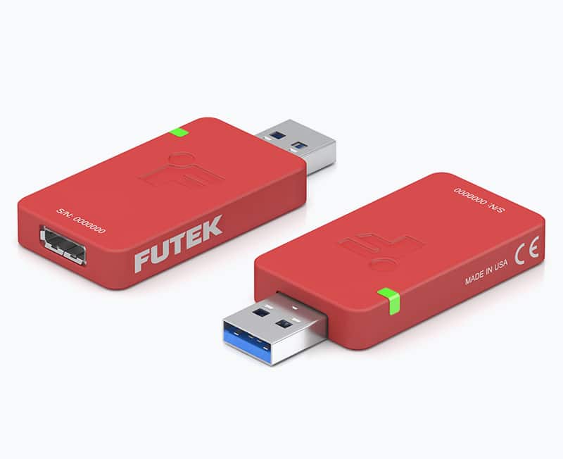
USB225 High Resolution & Speed USB Output Kit
FUTEK’s groundbreaking USB amplifiers offer a modern, single-unit turn-key solution that eliminates the need for external circuitry and power. When choosing a digital strain gauge signal conditioner, two critical parameters must be taken into consideration: noise-free resolution and sampling rate. The USB225 features an exceptionally high resolution (up to 20 bits) and a max sampling rate of 38,400 SPS. This unit also provides built-in fault detection and continuous monitoring of sensor health.
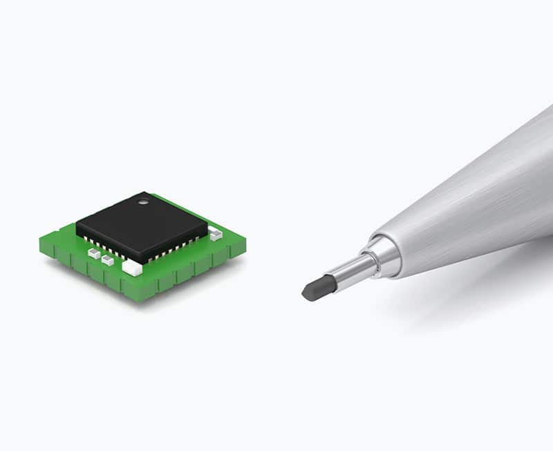
QIA128 Ultra-Low-Power Miniaturized Integrable Sampling System
QIA128 is a miniature embedded sampling system engineered for ultra-low power consumption of only 45 mW. Housed in an ultra compact 8mm x 8mm package, it is ideal for applications with tight spatial constraints such as medical devices and robotics. The QIA128 supports a bridge input resistance of 350 Ω to 5000 Ω, and can sample at up to 1,300 samples per second (SPS), delivering up to 18.4 Bits of Noise Free Resolution (NFR). Featuring both UART and SPI digital outputs, it also features built-in error detection and on-board temperature monitoring.
How do you integrate a load cell amplifier/signal conditioner into your system?
Offset and span calibration
Proper calibration of your signal conditioner and amplifier is paramount. In many standard industry approaches to calibration, offset and span aren’t accounted for independently, leading to errors. FUTEK has developed a variety of calibration methods to isolate the effects of offset and span to solve for the above issue.
Full system calibration
In a complete force measurement solution including a strain gauge-based sensor, cabling, and connectors, all components must be calibrated together as a system. This ensures the system’s accuracy while allowing you to use the force measurement solution out of the box, without having to manually adjust and calibrate each system component.
FUTEK’s calibration lab
As part of FUTEK’s commitment to deliver end-to-end solutions, our calibration lab will calibrate, set up, and optimize your system, providing you with a turnkey package of sensor, electronics, and calibration. As an A2LA-accredited calibration lab, FUTEK offers full system calibration for sensors with digital displays, amplifiers, and/or USB solutions. Our calibration procedures comply with ISO 17025 standards and our certification includes accreditation to ANSI/NCSL Z540-1.